D) Bottom Extrusions Assembly
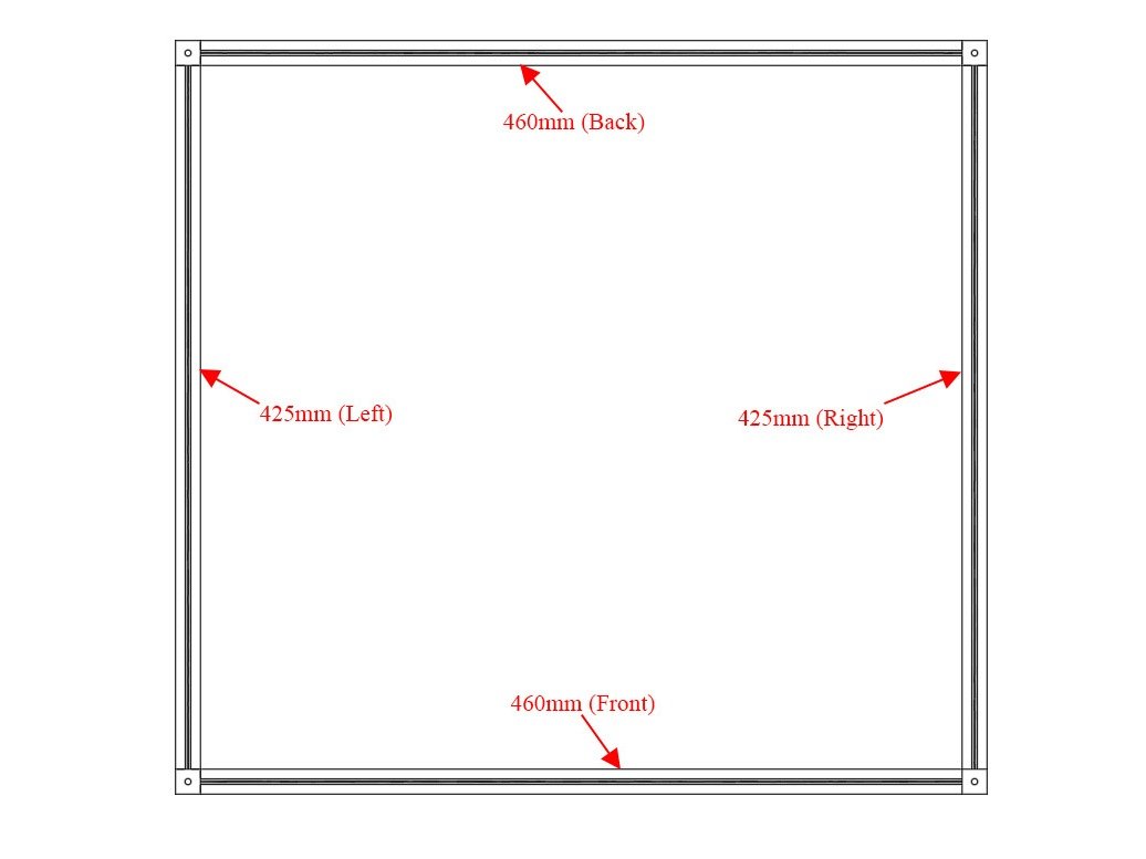
It's assumed that you're building a kit from Filastruder, and you've completed all previous sections. At the end of this section you should have a "bottom extrusions" assembly together for your RailCore frame.
Tools
Parts
Step 1 — Layout Bottom Frame
- Layout Bottom Frame as shown. Note that the corner cubes should have a small hole facing up.
- Caution The kit includes (2) untapped 425mm extrusions - for this step be sure to use the tapped extrusions.
- It is a good idea to mark each extrusion with a bit of masking tape on top, indicating which extrusion it is.
Step 2 — Install Corner Cube on Bottom Left Extrusion
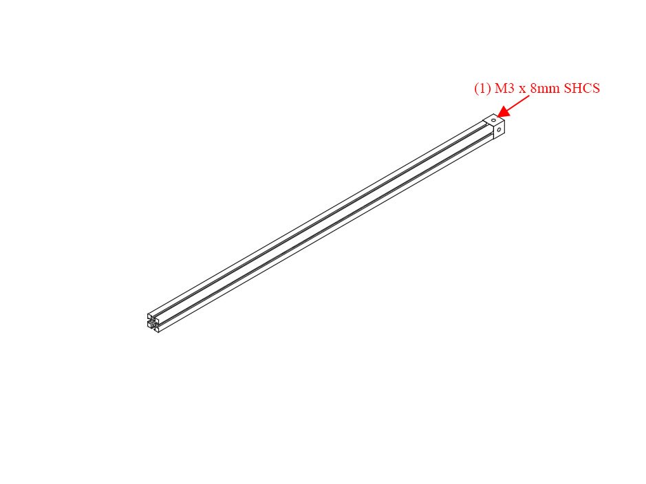
- Use (1) M3 x 8mm socket cap head screw to the 425mm bottom left extrusion. Note the orientation of the corner cube.
1 comment
Using the diagram above, it goes on the Back-Left corner of the Left bottom extrusion.
Step 3 — Add Hardware to Bottom Left Extrusion
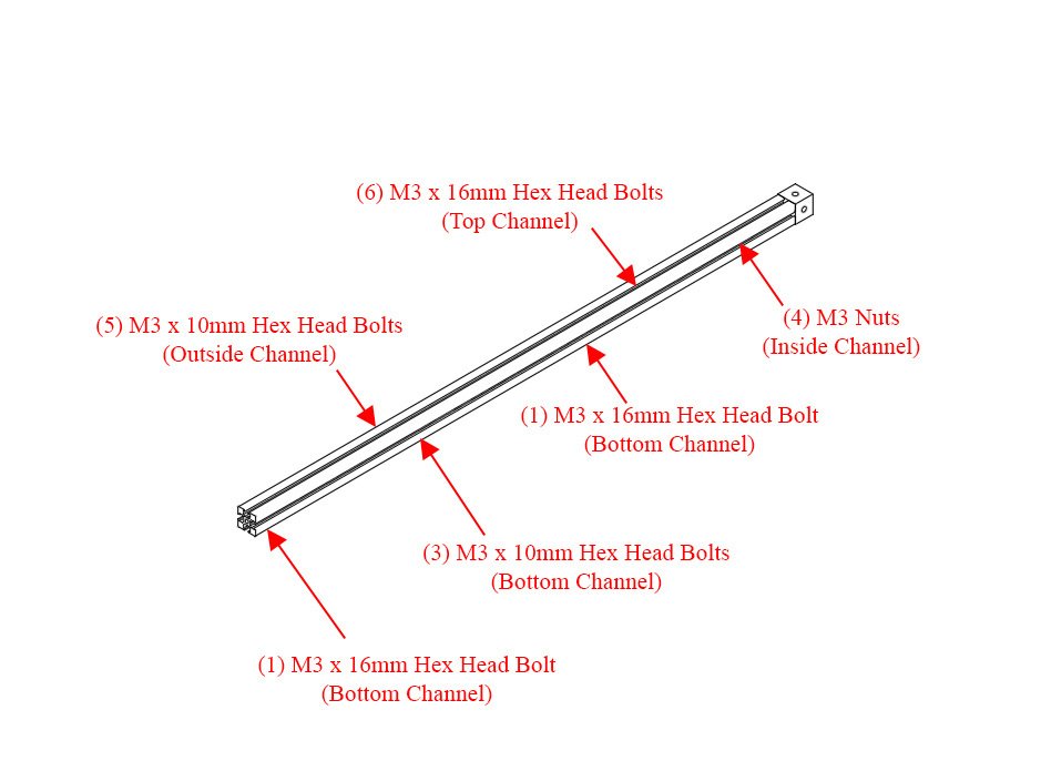
- Slide (6) M3 x 16mm hex head bolts into the top channel.
- Slide (5) M3 x 10mm hex head bolts into the outside channel.
- Slide (4) M3 nuts into the inside channel. Note: If using a metal bottom (base plate), these are not needed.
- In the bottom channel the order is (1) M3 x 16mm head head bolt, (3) M3 x 10mm hex head bolts, (1) M3 x 16mm hex head bolts. It is very important they're in this order, the longer bolts on the end are for attaching the feet.
1 comment
Note that this Cube end may be incorrectly rotated 180 degrees in the picture.
The Top Channel of the Bottom Left extrusion will have a small hole showing at the top of the cube.
Step 4 — Add Second Corner Cube to Bottom Left Extrusion
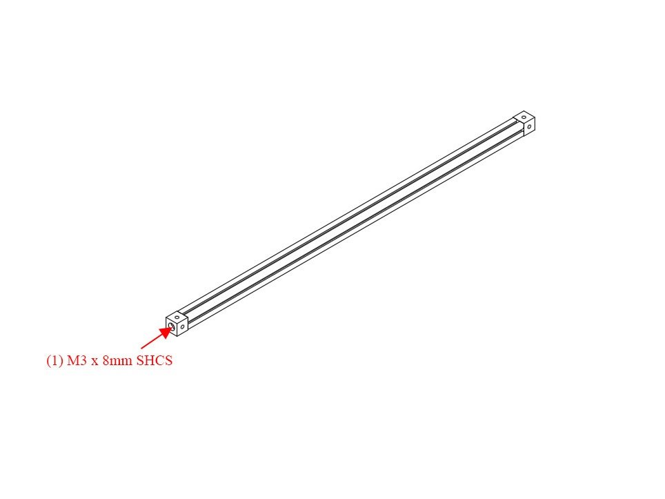
- Use (1) M3 x 8mm socket cap head screw to attach the second corner cube to the other end of the bottom left extrusion. Note hole orientation.
Step 5 — Add Bottom Front and Bottom Rear Extrusions
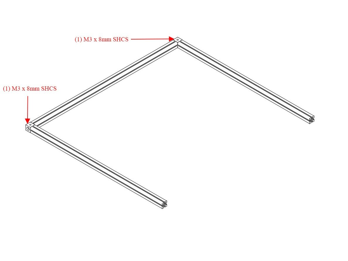
- Attach Bottom (2) 460mm Front and Bottom Back Extrusions using (1) M3 x 8mm Socket Cap Head Screw each.
Step 6 — Add Hardware into Bottom Front and Bottom Rear Extrusions
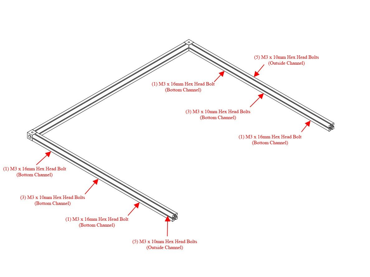
- Slide (5) M3 x 10mm hex head bolts in the outside channel of the bottom rear extrusion.
- The bottom channel of the bottom rear extrusion gets (1) M3 x 16mm hex head bolt, (3) M3 x 10mm hex head bolts, and (1) M3 x 16mm hex head bolt, in that order.
- Slide (5) M3 x 10mm hex head bolts in the outside channel of the bottom front extrusion.
- The bottom channel of the bottom front extrusion gets (1) M3 x 16mm hex head bolt, (3) M3 x 10mm hex head bolts, and (1) M3 x 16mm hex head bolt, in that order.
- Set this assembly aside, so you can assemble the bottom right extrusion.
1 comment
Note that the Corner Cubes in the picture for Step 6 may be shown incorrectly. They will have Small Hole on top, Large hole facing the bottom.
Step 7 — Install Corner Cube on Bottom Right Extrusion
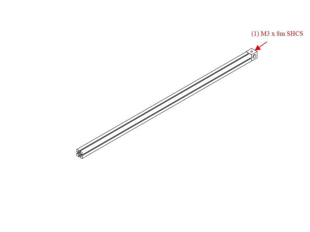
- Use (1) M3 x 8mm Socket Cap Head Screw to add a corner cube to the bottom right 425mm extrusion. Note the orientation of the corner cube - a small hole needs to face up.
Step 8 — Add Hardware into Bottom Right Extrusion
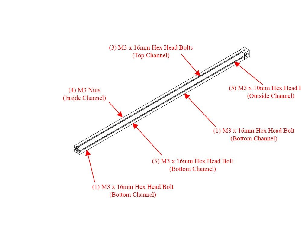
- Slide (3) M3 x 16mm hex head bolts in the top channel
- Slide (4) M3 nuts in the inside channel. Note: If using a metal bottom (base plate), these are not needed.
- Slide (5) M3 x 10mm hex head bolts in the outside channel.
- In the bottom channel add the following hardware in this order: (1) M3 x 16mm hex head Bolt, (3) M3 x 10mm hex head bolts, (1) M3 x 16mm hex head bolt.
1 comment
In diagram- Bottom Channel, 3 M3 x 16 should be 3 M3 x10
Step 9 — Add Second Corner Cube to Bottom Right Extrusion
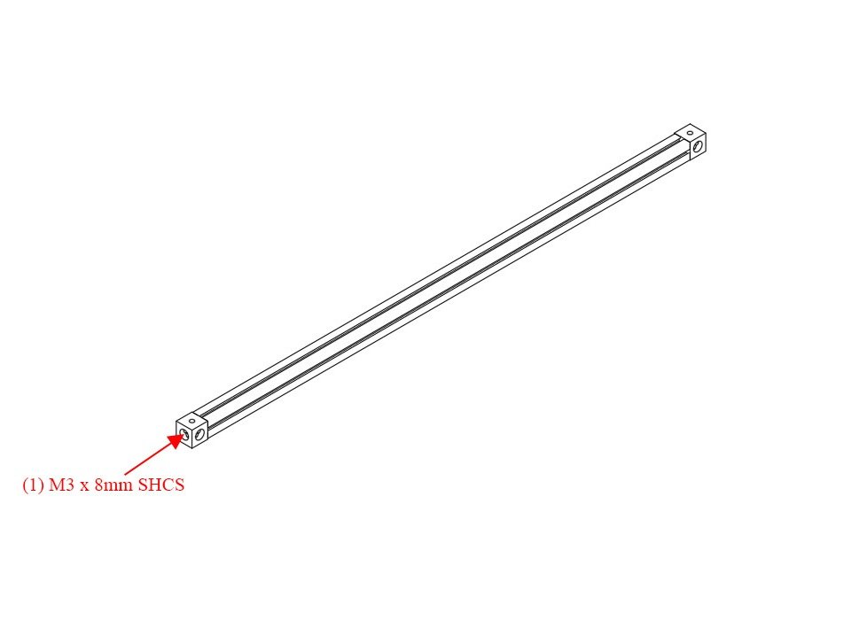
- Use (1) M3 x 8mm Socket Head Cap Screw to attach a second corner cube to the bottom right extrusion. Note the orientation of the corner cube - a small hole should be facing up.
Step 10 — Attach Bottom Right Extrusion to the Rest of the Bottom Frame
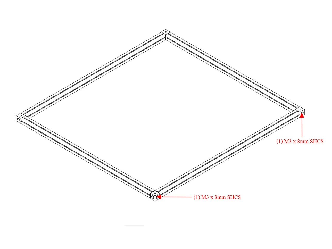
- Use (2) M3 x 8mm Socket Cap Head Screws to attach the bottom right extrusion to the rest of the bottom frame assembly from earlier.
1 comment
If using the HDPE base, make sure the two bottom stiffening braces fit between these extrusions. I had the whole frame built with sides bolted on and the bottom braces won’t fit between the extrusions (Filastruder kit). I already had everything square so I it was a bit painful to loosen an extrusion and side panel to fit these in and then adjust for squareness again.
Originally at https://railcore.dozuki.com/Guide/D)+Bottom+Extrusions+Assembly/3
1 comment
If building with the optional 713Maker Metal Baseplate, then it’s easiest to build the bottom extrusion frame directly onto the plate in the steps below.
Each downward-facing bolt goes through the baseplate for attachment with an M3 Locknut. Assemble frame, then align it flat to the baseplate before tightening corner cubes.
Access to the corner cubes is still needed, so do not bolt the Feet onto the M3x16 long nuts just yet. Wait until mounting the upright extrusions next.