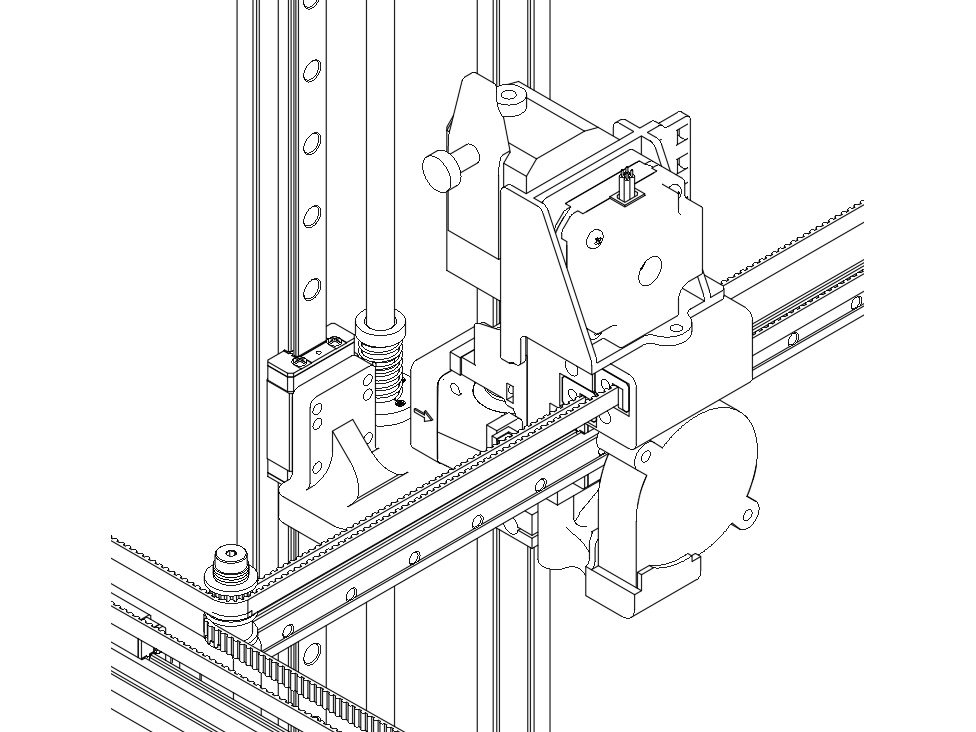
RailCore II 300ZL Kit — complete build

A) Introduction

Background

RailCore® II is a CoreXY-based RepRap 3D printer designed by J. Steve White and Tony Akens and published under the CC Attribution Only license. The initial collaboration behind the RailCore started in the #reprap IRC channel and centered on some common goals for a new printer design.

These goals were:

  • CoreXY motion
  • All linear rails for movement
  • Space and cost-efficient with an enclosable frame
  • Key components being printable or able to be milled
  • Flexibility, customizability, and scalability built into the design
  • Professional-looking
  • Can be self-sourced

History

J. Steve White had previously built the Railcore - the alpha version of this printer. Lessons were learned and the design on the new printer began. All design work was done in Fusion360.

As it progressed, we decided to publish this printer in an open, documented format for others to build as well.

Overview

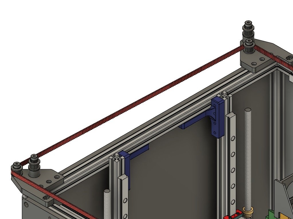
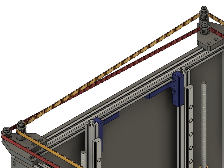
The frame is designed to use 1515 aluminum extrusions. This was a space-efficient choice, which makes building the printer easier, as standard M3 hardware fits nicely into the extrusion like T-Nuts would. To add rigidity, we use sides made from HDPE to stiffen the frame. (These can alternatively be cut out of any material you prefer, including melamine, plywood, acrylic and aluminum.) The total cost for the actual frame components (extrusion, corner cubes, and sides) is roughly $100 USD.

Notable aspects of the design include:

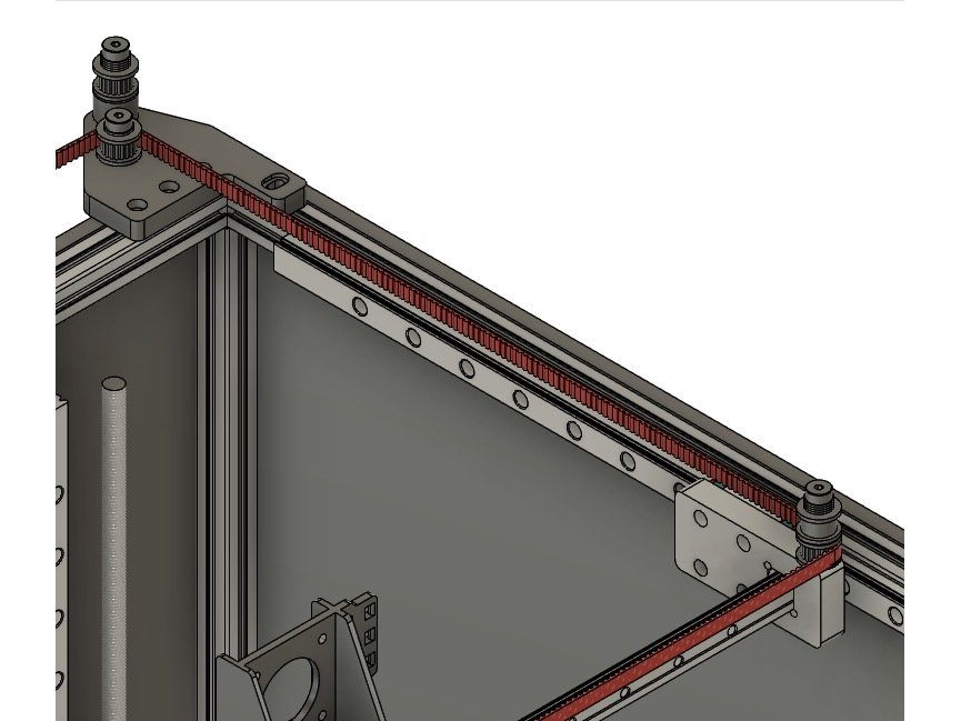
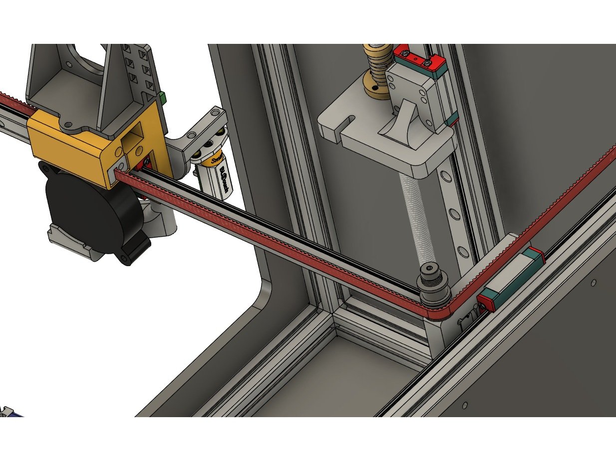
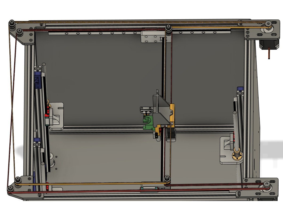
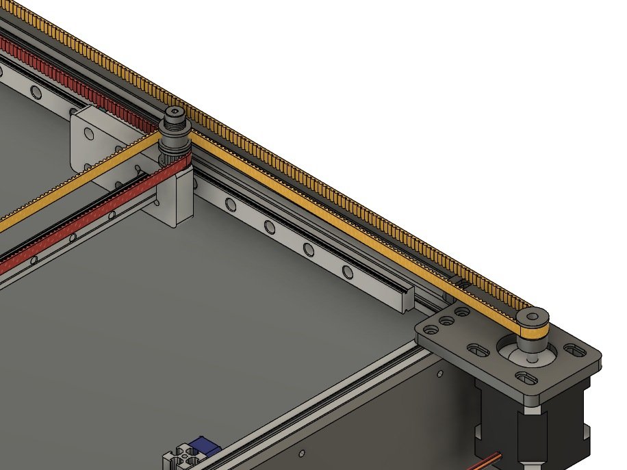
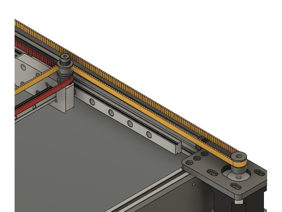
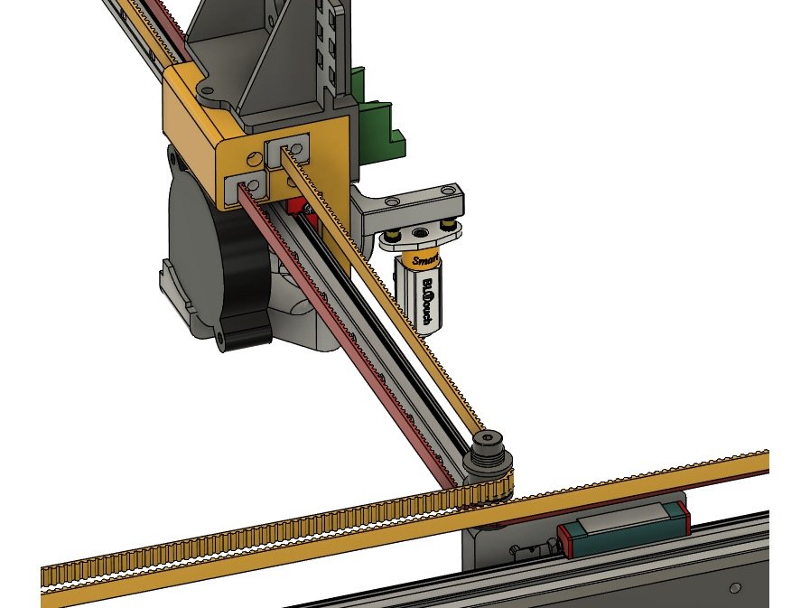
  • 3 trapezoidal lead screw Z-axis, stacked idlers, and duo-planar belt path
  • The electronics in the design are the Duet (Wifi or Ethernet), Duex2/5, 24v PSU and 0.9 degree steppers
  • We use an E3D v6 for the design, as it’s the most common hotend at this time
  • Support for other hotends such as Volcano, Mosquito, and many others are also available
  • Semi-direct drive or full bowden are both supported

The current railcore kit is assembled and sold by Filastruder. This guide should cover the "standard" kit configurations they sell. It may work with other variations including self source builds, and "add-ons", with minor variation.

If you need assistance with your build, a strong community of support is available at our discord channel: https://discord.gg/sShTCJS

A special thanks to Filastruder, Duet3d, E3D, SeeMeCNC, 713Maker ,Mandala Roseworks, and Project R3D for supporting the project.

RailCore® is a registered trademark of RailCore Labs, LLC
B) Prep

Step 1 — Install brass inserts

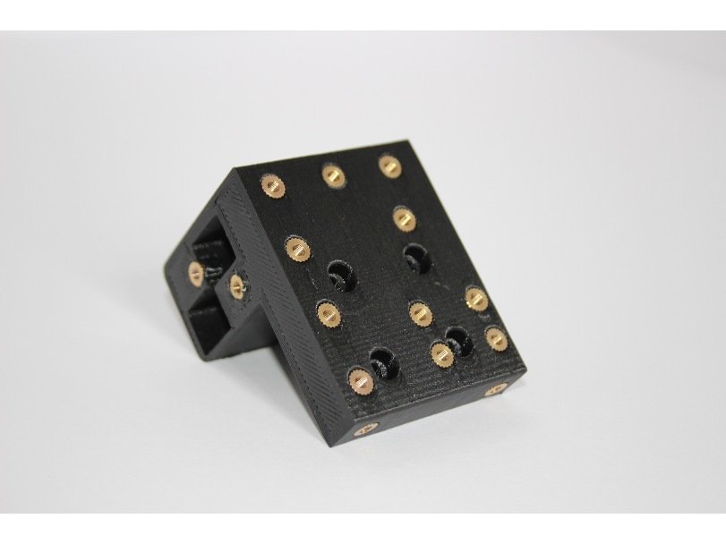
  • Caution You need to use a soldering iron to carefully sink the brass inserts into the printed Y carriage. Sink the inserts in 2/3 of the way, then press the carriage against a flat metal surface to get them flush.
  • Note After placing each insert you may need to clear the channel by running a tap or bolt down through the insert and into the plastic. (Be very careful not to cross thread your inserts!)
  • Note Here's a good article about setting the brass heat set inserts: click here.
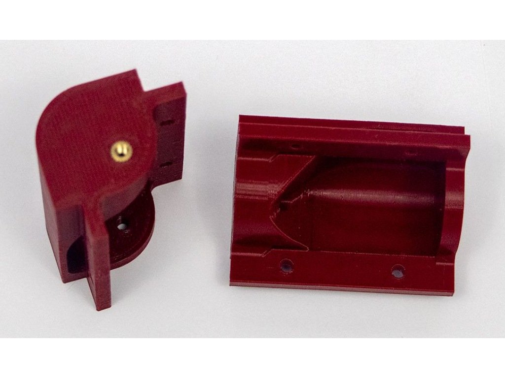
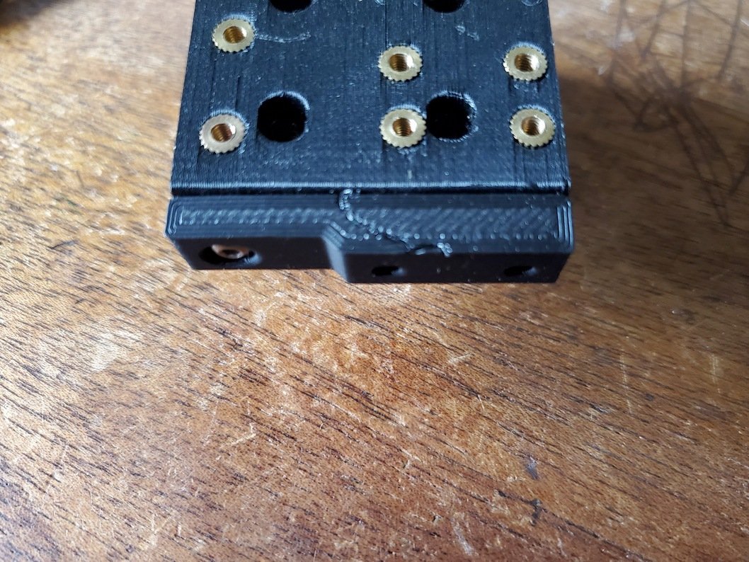
  • The Y carriage gets (18) 3mm brass inserts, as in the picture. (Note: there are also two on the back side, and one on the top. Not all RailCore kits include the optional one on the top, requiring only 17 inserts)
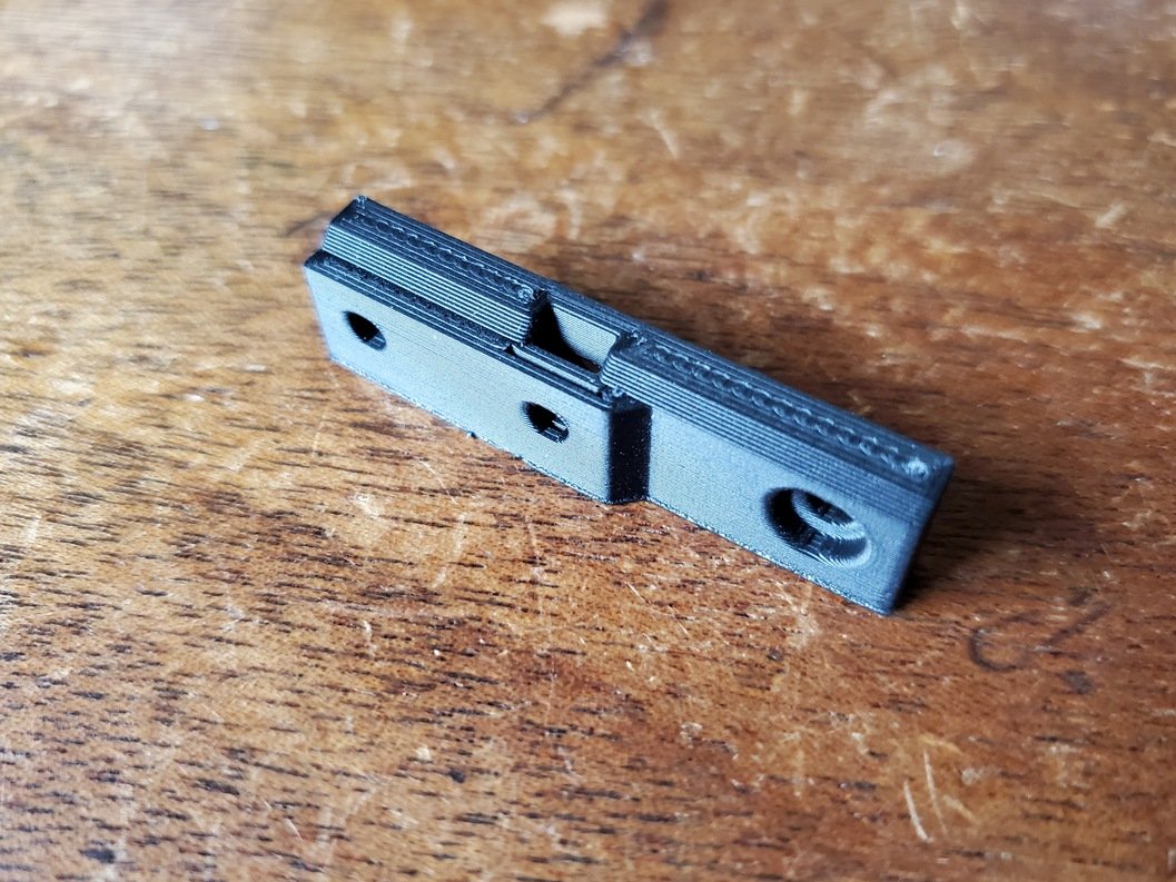
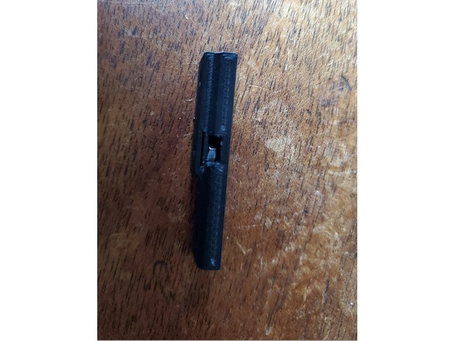
  • Each Electronics Box corner gets one (1) brass insert. One end is thicker, to make putting the insert in easier. Be sure to place the inserts into the thick end, as in Picture 2.

Step 2 — Install the Keenovo Heater

  • Keenovo has an install guide at this link which will download a PDF file for reference.
  • Follow Section 4.2 to install using the pre-installed adhesive.
  • The keenovo goes centered on the bottom of the bed (The thermistor groove goes on the top).
  • The wires should exit on the same side of the bed as the thermistor.

Step 3 — Installing the bed thermistor

  • Note Installing the thermistor in the bed now will make it easier to install the assembled bed in the printer frame in a later step. A youtube video of this process is here.
  • Caution Be careful with the thermistor, the bead is glass, and if it’s broken it won’t give a reading, or will be way off. The thermistors have very long leads on them and are protected in rubber all the way up to the bead.
  • Place the thermistor into the channel in the top of the bed.
    • Cover about 10mm of the thermistor leads near the glass bead in RTV.
    • Cover another 10mm of the lead near the side of the bed.
    • Use a razor blade to clean up the excess RTV; there should be no RTV higher than the channel in the bed, and none on the bed surface itself.
  • Set your bed aside and let the RTV dry while you continue with the following steps.
  • Note If you want to continue working with the bed on a later step before the RTV is fully dry, you can cover the groove with Kapton tape until it’s dry. Use a razor blade to cut the tape along the sides of the groove, and leave the part on top of the RTV, so it doesn't pull it out of the groove.

Step 4 — Install the bed surface

  • Once the RTV has cured and you've cut away or removed the kapton tape, you can install the bed surface.
  • If you're using a magbed, this just involves putting the magplate on.
  • If using a stick on surface, remove the backing, and work from one corner. Use a straight edge to seal the surface to the bed, to avoid any air bubbles as you go.

Step 5 — Assemble the hotend

  • Note You will need to assemble your hotend prior to attaching it to the Y carriage in a later step. The electrical connections to the hotend components will be completed later as well.
  • Since the RailCore is so flexible, there are numerous hotends to choose from and you should follow the assembly instructions for your particular hotend and manufacturer below:

C) Top Extrusions Assembly

It's assumed that you're building a kit from Filastruder, and you've completed all previous sections. At the end of this section you should have a "top extrusions" assembly together for your RailCore frame.

Step 1 — Lay Out Top Extrusions

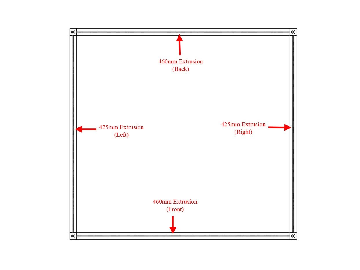
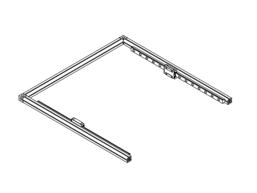
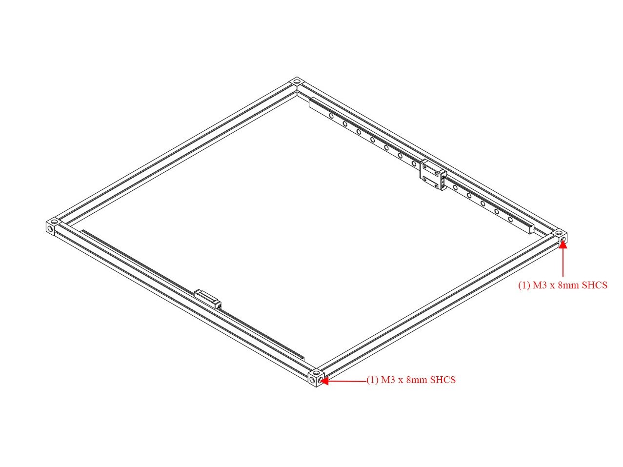
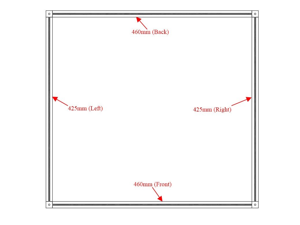
  • Lay Out Top Extrusions as pictured
  • Caution The kit includes (2) untapped 425mm extrusions - for this step be sure to use the tapped extrusions.
  • It can be helpful to use masking tape to add a label to the top of each extrusion indicating which it is (Top Back, Top Left, etc)
  • Be sure the Corner cubes have a larger hole facing up, smaller hole facing down.

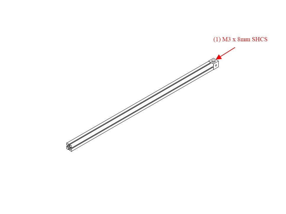
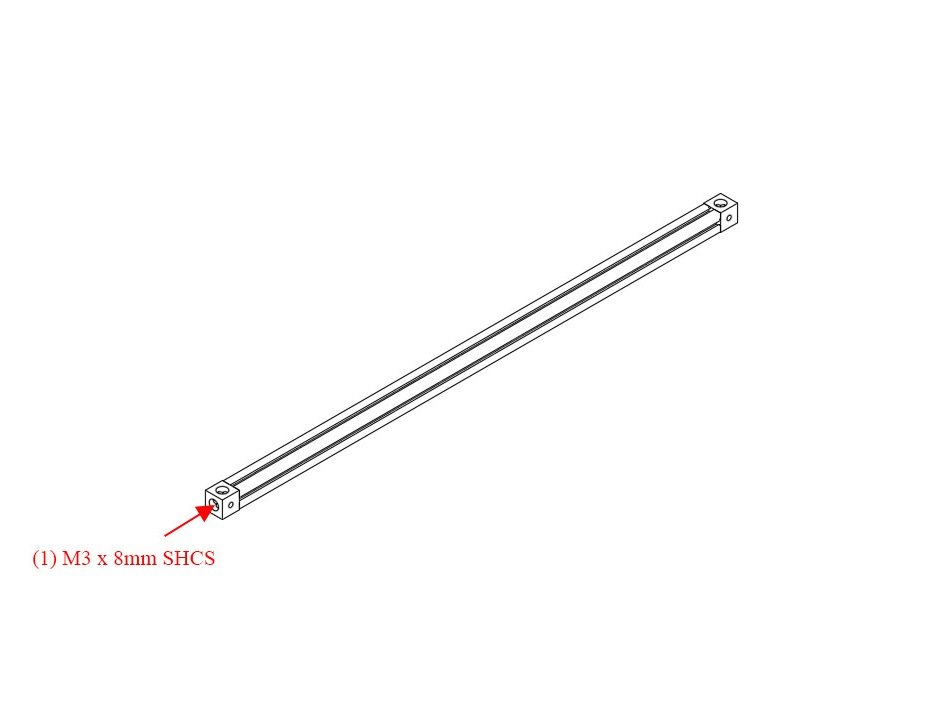
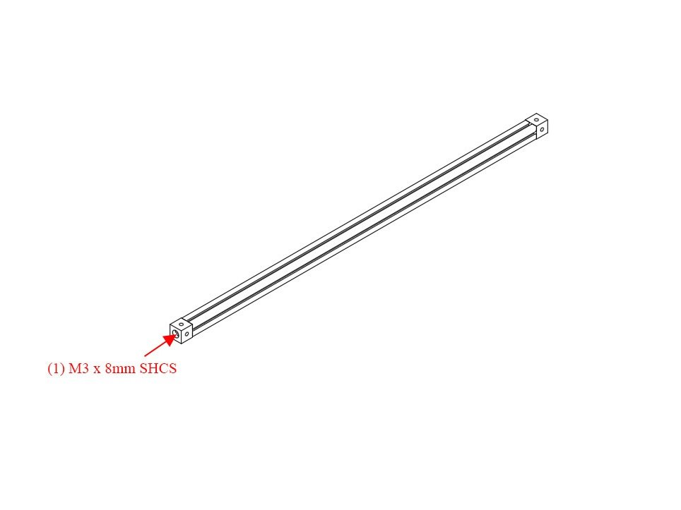
Step 2 — Bolt Corner Cube to Top Left Extrusion

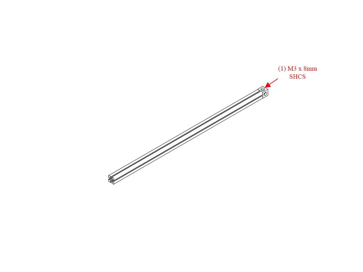
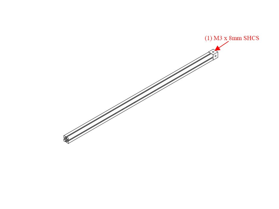
  • Bolt Corner Cube to Top Left 425mm Extrusion using (1) M3 x 8mm Socket Head Cap Screw
  • Note Note on the corner cube, the small hole is pointing to the right in this image

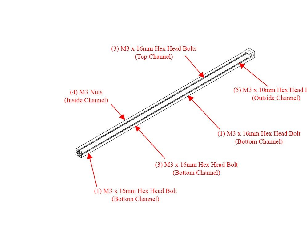
Step 3 — Add Hardware to Top Left Extrusion

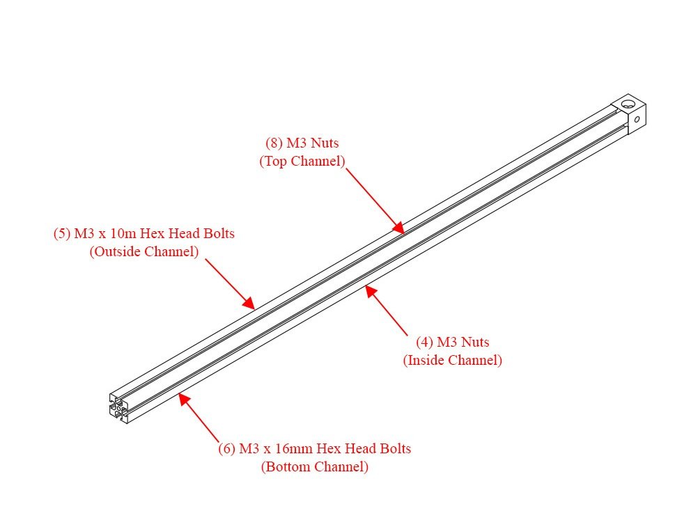
  • Hold the Extrusion as it will be oriented on the printer (make sure the big hole on the corner cube faces up)
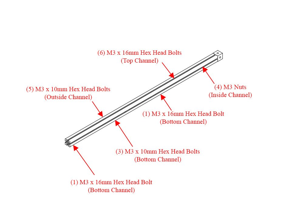
  • Slide (8) M3 nuts into the top channel (If you're installing a halo, add 6 additional M3 nuts for a total of 14)
  • Slide (5) M3 x 10mm Hex Head Bolts in the outside channel
  • Slide (4) M3 nuts in the inside channel
  • Slide (6) M3 x 16mm Hex Head bolts in the bottom channel
  • Note Note on the corner cube, the small hole is pointing to the right in this image

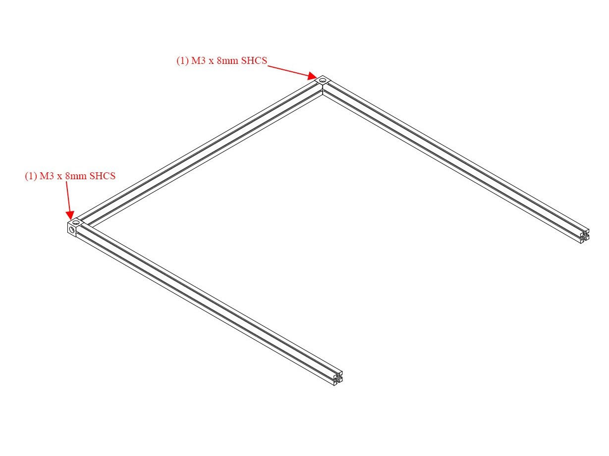
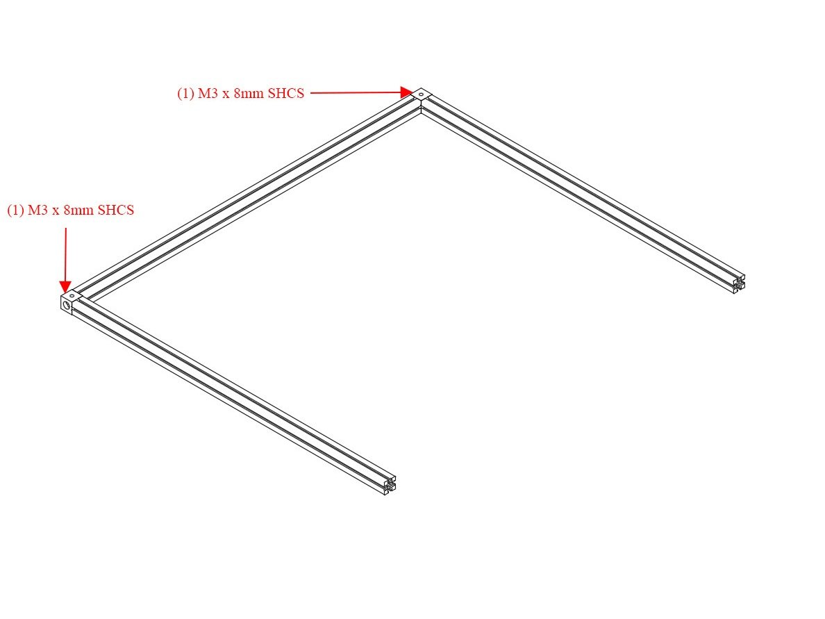
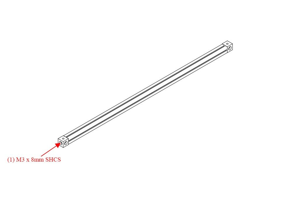
Step 4 — Attach Second Corner Cube to Top Left Extrusion

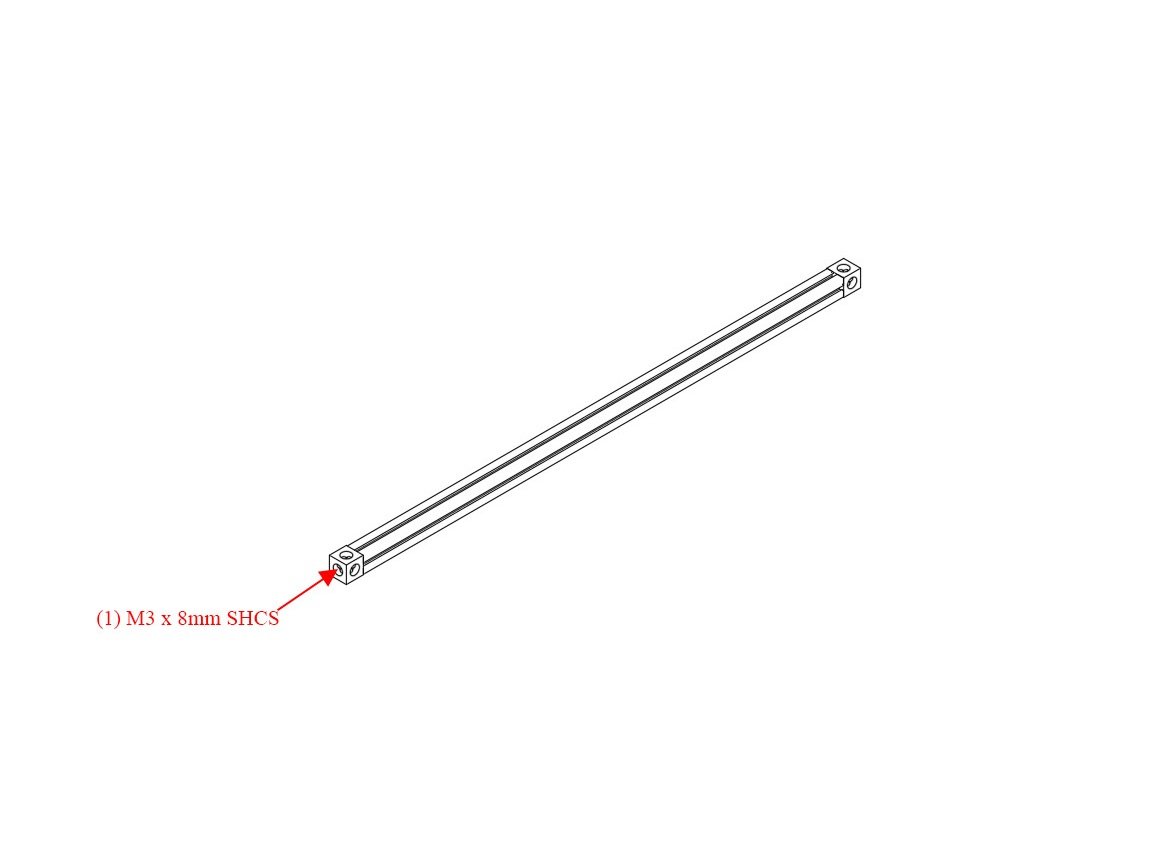
  • Attach Second Corner Cube to Top Left Extrusion using (1) M3 x 8mm socket cap head screw. Be sure the large hole is up, small hole is down.
  • Note Note on both corner cubes, the small hole is pointing to the right in this image

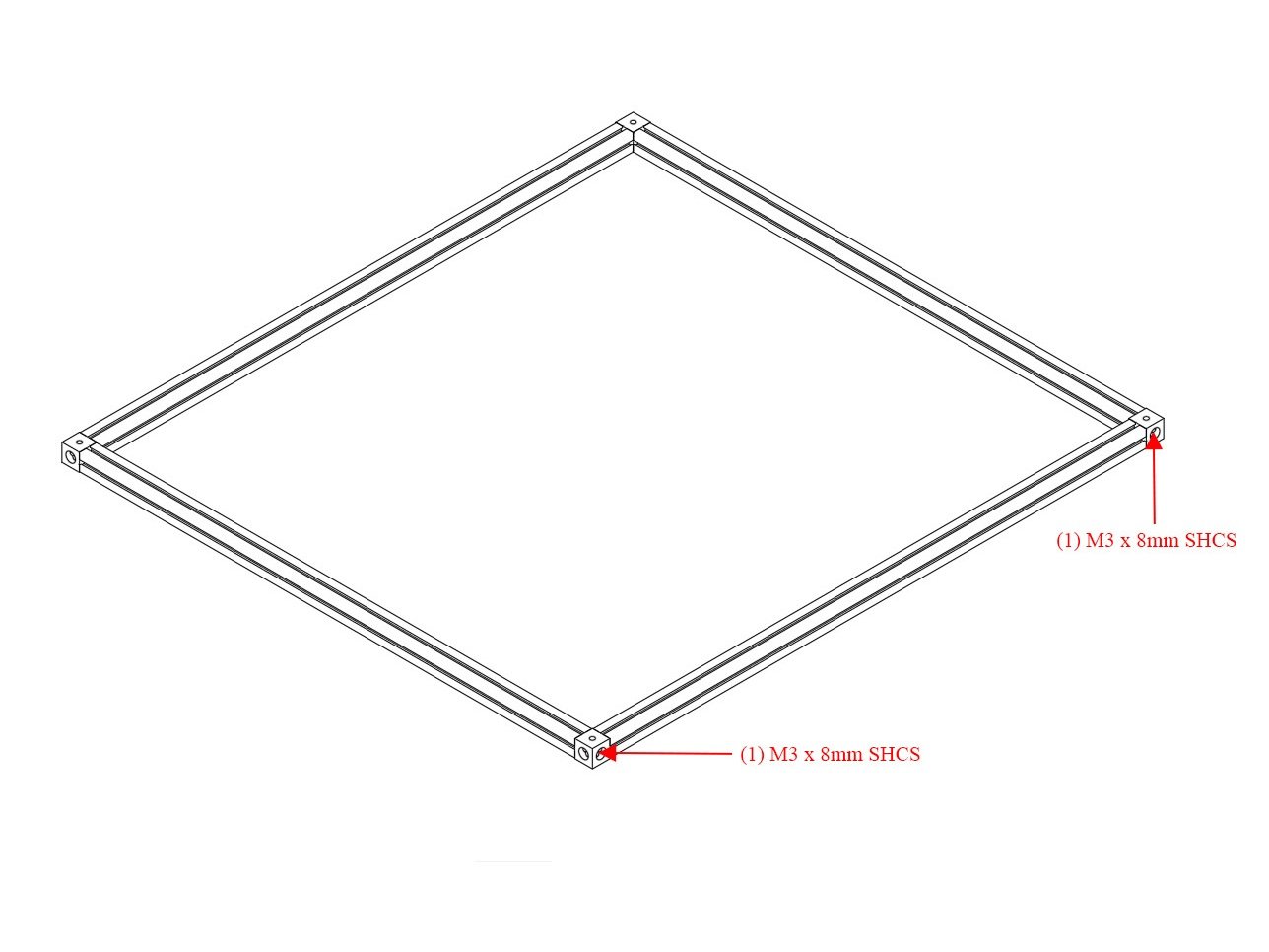
Step 5 — Attach Top Front and Top Back Extrusions

  • Attach the (2) 460mm Top Front and Top Back Extrusions using (1) M3 x 8mm socket cap head screw each.

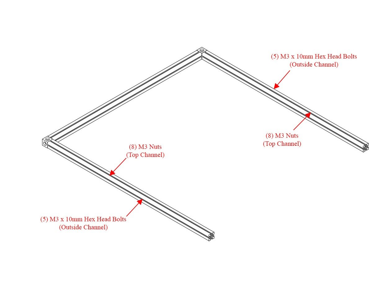
Step 6 — Add Hardware to Top Front and Top Back Extrusions

  • (5) M3 x 10mm Hex head bolts go in the outside channel of the back extrusion.
  • (8) M3 nuts go in the top channel of the back extrusion (if installing the optional Halo, add six (6) more nuts in this channel for a total of 14).
  • (8) M3 nuts go in the top channel of the front extrusion (if installing the optional Halo, add six (6) more nuts in this channel for a total of 14).
  • (5) M3 x 10mm Hex Head Bolts go in the outside channel of the front extrusion.

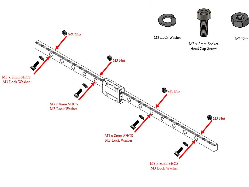
Step 7 — (2x) Install M3 Hardware into Linear Rail

  • Use a bit of masking tape to keep your carriage from sliding off your linear rail.
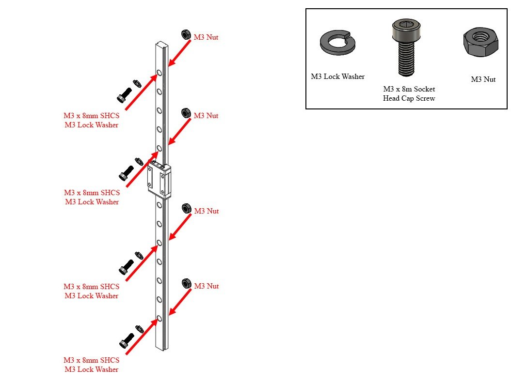
  • Select 4 evenly spaced holes in your linear rail. (roughly 3 empty holes between each bolt)
  • Place a lock washer on (1) M3 x 8mm socket cap head screw, and place it into one of the holes selected. Loosely thread on (1) M3 nut to the bolt. DO NOT TIGHTEN THEM FULLY. The M3 nut only needs to be threaded onto the tip of the bolt, you want a gap between the nut and the back of the rail. Repeat for the other three (3) holes.
  • Repeat the above steps for the other 400mm rail.
  • Caution It is highly recommended to use a bit of masking tape to keep the carriage from sliding off of the linear rail.

Step 8 — Attach Linear rail to Top Front and Top Back Extrusions

  • Attach Linear rail to Top Front and Top Back Extrusions by sliding the M3 nuts into the inside channel on the extrusion.
  • Roughly center the extrusion, and then snug up the bolts.
  • Caution Do not overtighten the bolts, you just need them snug for now. They'll be tightened later.
  • Caution It is highly recommended to use a bit of masking tape to keep the carriage from sliding off of the linear rail.

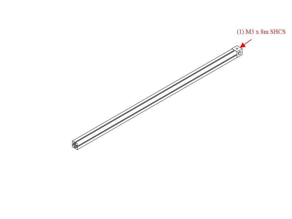
Step 9 — Attach Corner Cube to Top Right Extrusion

  • Set aside the rest of your top extrusion assembly for now, so we can work on the top right extrusion.
  • Attach a corner cube to the right 425mm extrusion using (1) M3 x 8mm socket cap head screw.

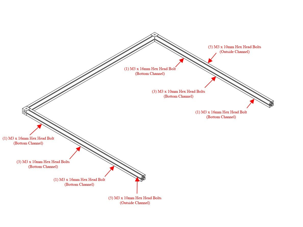
Step 10 — Add Hardware to Top Right Extrusion

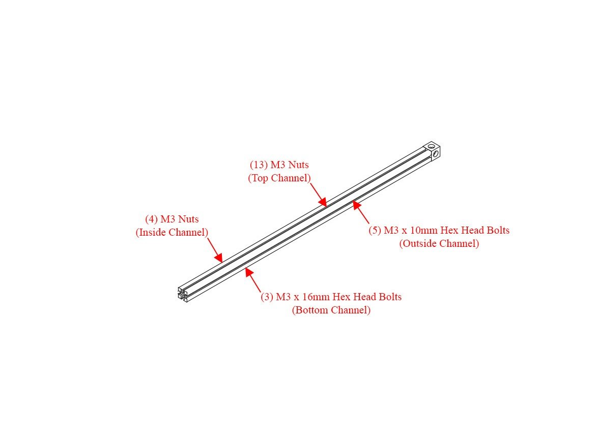
  • Slide (13) M3 nuts into the top channel (if installing the optional Halo, add six (6) more nuts in this channel for a total of 19)
  • Slide (4) M3 nuts into the inside channel
  • Slide (5) M3 x 10mm Hex Head Bolts into the outside channel
  • Slide (3) M3 x 16mm Hex Head Bolts into the bottom channel
  • Caution Be sure the orientation of the corner cube is correct. A large hole should face up, a small hole should be facing down, and a small hole should be facing towards the inside channel

Step 11 — Attach Second Corner Cube to Top Right Extrusion

  • Attach Second Corner Cube to Top Right Extrusion using (1) M3 x 8mm socket cap head screw.

Step 12 — Attach Top Right Extrusion to the Rest of the Top Extrusion Assembly

  • Attach Top Right Extrusion to the rest of the Top Extrusion Assembly using (2) M3 x 8mm socket cap head screws.

D) Bottom Extrusions Assembly

It's assumed that you're building a kit from Filastruder, and you've completed all previous sections. At the end of this section you should have a "bottom extrusions" assembly together for your RailCore frame.

Step 1 — Layout Bottom Frame

  • Layout Bottom Frame as shown. Note that the corner cubes should have a small hole facing up.
  • Caution The kit includes (2) untapped 425mm extrusions - for this step be sure to use the tapped extrusions.
  • It is a good idea to mark each extrusion with a bit of masking tape on top, indicating which extrusion it is.

Step 2 — Install Corner Cube on Bottom Left Extrusion

  • Use (1) M3 x 8mm socket cap head screw to the 425mm bottom left extrusion. Note the orientation of the corner cube.

Step 3 — Add Hardware to Bottom Left Extrusion

  • Slide (6) M3 x 16mm hex head bolts into the top channel.
  • Slide (5) M3 x 10mm hex head bolts into the outside channel.
  • Slide (4) M3 nuts into the inside channel. Note: If using a metal bottom (base plate), these are not needed.
  • In the bottom channel the order is (1) M3 x 16mm head head bolt, (3) M3 x 10mm hex head bolts, (1) M3 x 16mm hex head bolts. It is very important they're in this order, the longer bolts on the end are for attaching the feet.

Step 4 — Add Second Corner Cube to Bottom Left Extrusion

  • Use (1) M3 x 8mm socket cap head screw to attach the second corner cube to the other end of the bottom left extrusion. Note hole orientation.

Step 5 — Add Bottom Front and Bottom Rear Extrusions

  • Attach Bottom (2) 460mm Front and Bottom Back Extrusions using (1) M3 x 8mm Socket Cap Head Screw each.

Step 6 — Add Hardware into Bottom Front and Bottom Rear Extrusions

  • Slide (5) M3 x 10mm hex head bolts in the outside channel of the bottom rear extrusion.
  • The bottom channel of the bottom rear extrusion gets (1) M3 x 16mm hex head bolt, (3) M3 x 10mm hex head bolts, and (1) M3 x 16mm hex head bolt, in that order.
  • Slide (5) M3 x 10mm hex head bolts in the outside channel of the bottom front extrusion.
  • The bottom channel of the bottom front extrusion gets (1) M3 x 16mm hex head bolt, (3) M3 x 10mm hex head bolts, and (1) M3 x 16mm hex head bolt, in that order.
  • Set this assembly aside, so you can assemble the bottom right extrusion.

Step 7 — Install Corner Cube on Bottom Right Extrusion

  • Use (1) M3 x 8mm Socket Cap Head Screw to add a corner cube to the bottom right 425mm extrusion. Note the orientation of the corner cube - a small hole needs to face up.

Step 8 — Add Hardware into Bottom Right Extrusion

  • Slide (3) M3 x 16mm hex head bolts in the top channel
  • Slide (4) M3 nuts in the inside channel. Note: If using a metal bottom (base plate), these are not needed.
  • Slide (5) M3 x 10mm hex head bolts in the outside channel.
  • In the bottom channel add the following hardware in this order: (1) M3 x 16mm hex head Bolt, (3) M3 x 10mm hex head bolts, (1) M3 x 16mm hex head bolt.

Step 9 — Add Second Corner Cube to Bottom Right Extrusion

  • Use (1) M3 x 8mm Socket Head Cap Screw to attach a second corner cube to the bottom right extrusion. Note the orientation of the corner cube - a small hole should be facing up.

Step 10 — Attach Bottom Right Extrusion to the Rest of the Bottom Frame

  • Use (2) M3 x 8mm Socket Cap Head Screws to attach the bottom right extrusion to the rest of the bottom frame assembly from earlier.

E) Upright Extrusion / Frame Final Assembly

It's assumed that you're building a kit from Filastruder, and you've completed all previous sections. At the end of this section you should have a complete frame assembled for your RailCore.

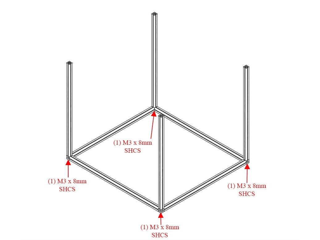
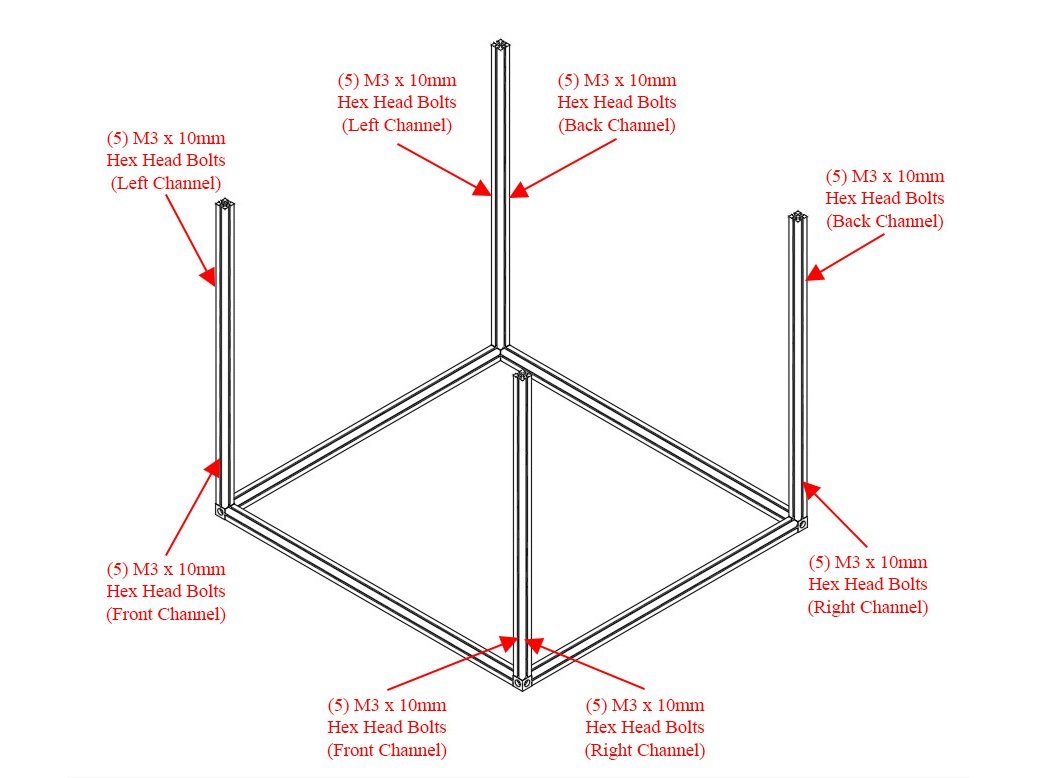
Step 1 — Add the Upright Extrusions to your Bottom Frame Assembly

  • Use (1) M3 x 8mm Socket Cap Head Screw to attach each of the (4) 415mm (715mm for ZLT) upgright extrusions to the corner cubes on the bottom frame assembly. Note: It can be helpful to prop the bottom frame assembly up on some old filament spools so that the upright extrusions remain vertical.

Step 2 — Add Hardware into the Upright Extrusions

  • Slide (5) M3 x 10mm hex head head bolts in both of the outside channels on each upright extrusion.
  • Caution For the ZLT you need (7) M3 x 10mm hex head bolts in each channel instead of (5). These bolts are in the ZLT supplement bag.

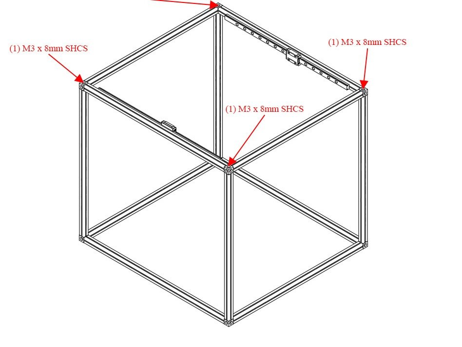
Step 3 — Attach Top Frame Assembly to Upright Bottom Frame Assembly

  • Use (4) M3 x 8mm Socket Cap Head Screws to attach the top extrusion assembly to the upright extrusions.
  • Congratulations! You've completed the frame assembly for your RailCore II 300ZL/300ZLT.

F) Z Installation

It's assumed that you're building a kit from Filastruder, and you've completed all previous sections. At the end of this section you should have your Z axis attached to your frame assembly.

Step 1

  • Newer Filastruder kits use Socket Cap Head Screws, use them in place of all button head screws in this section.

Step 2 — Install Z Brackets

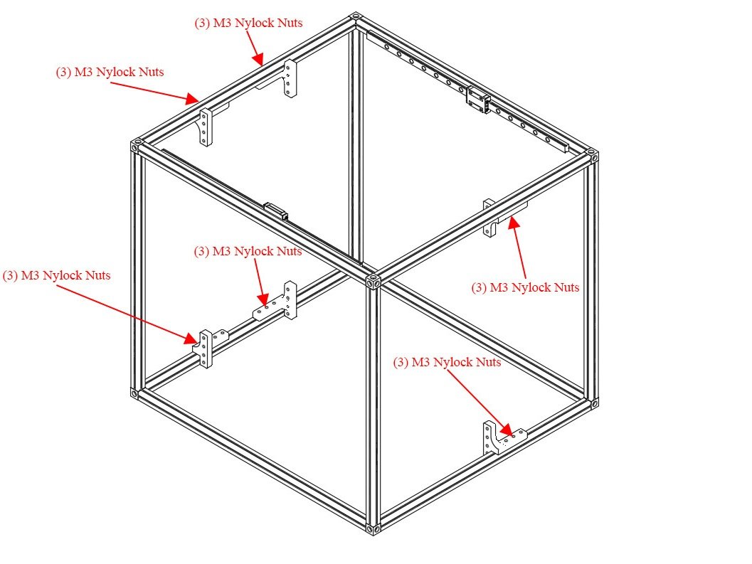
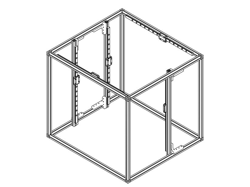
  • Find the Z brackets in the parts and align each as follows.
  • Note the orientation of each bracket. It is CRITICAL that the brackets all face the correct way.
  • On the left, the long horizontal ends of the brackets point towards each other. The vertical ends of the brackets face out towards the front and back of the frame
  • On the right the vertical ends of the brackets face the front of the frame.
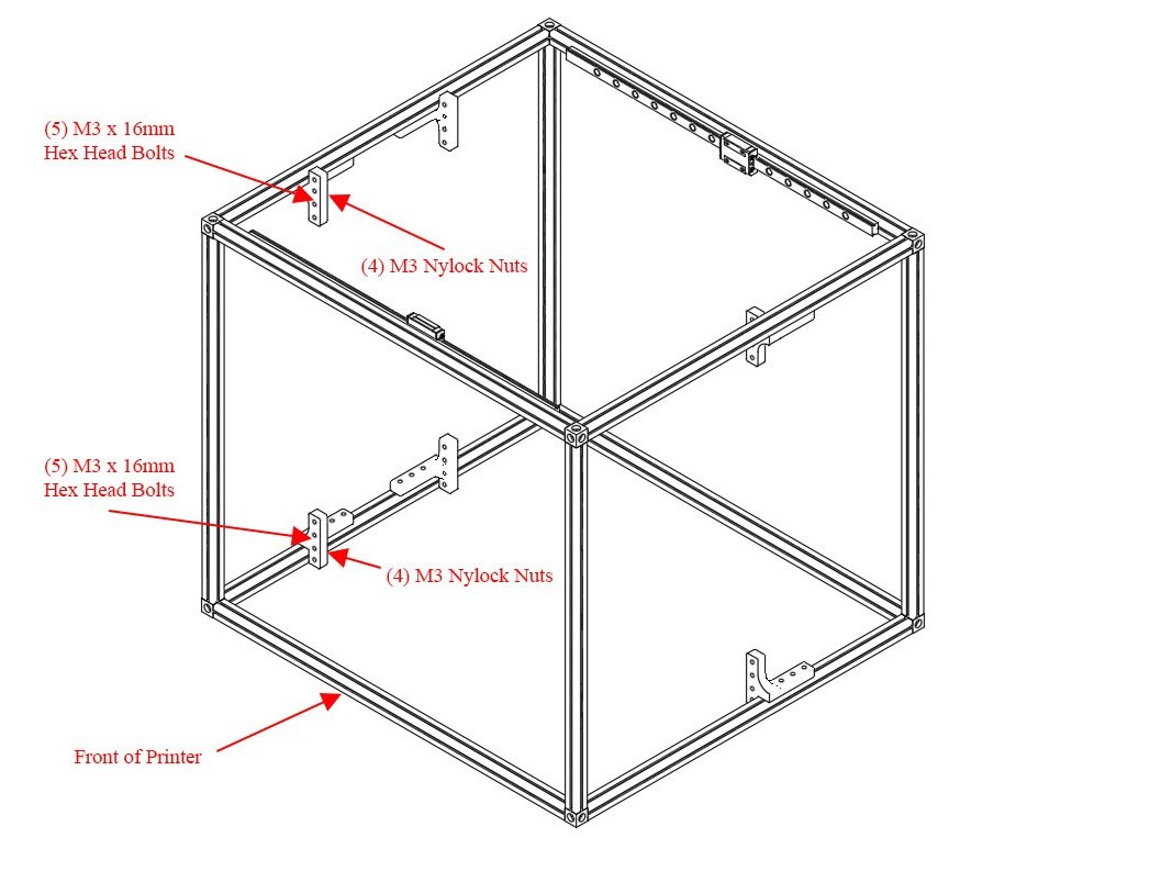
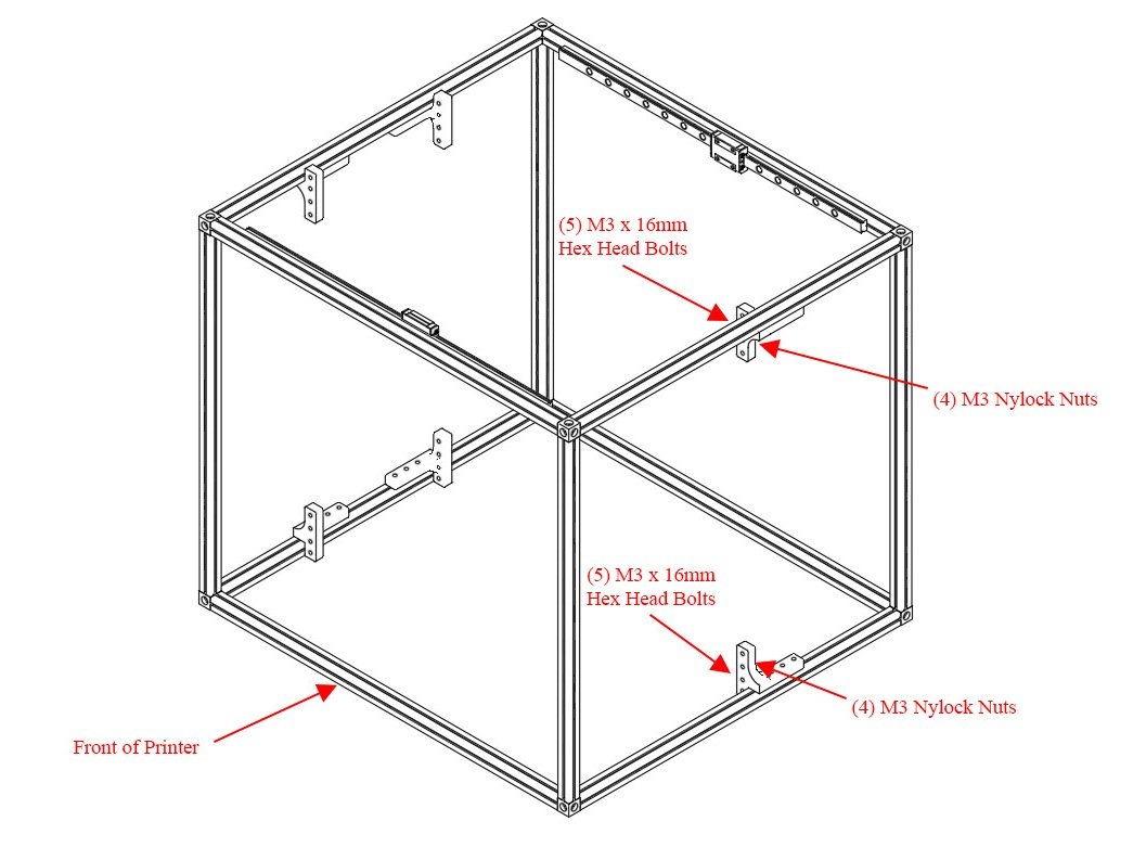
  • Loosely install each Z bracket using (3) M3 Nylock Nuts. Leave them loose enough you can easily move them, there should be about 60mm between them, and the front one about 110mm from the front of the frame, though you can adjust later.

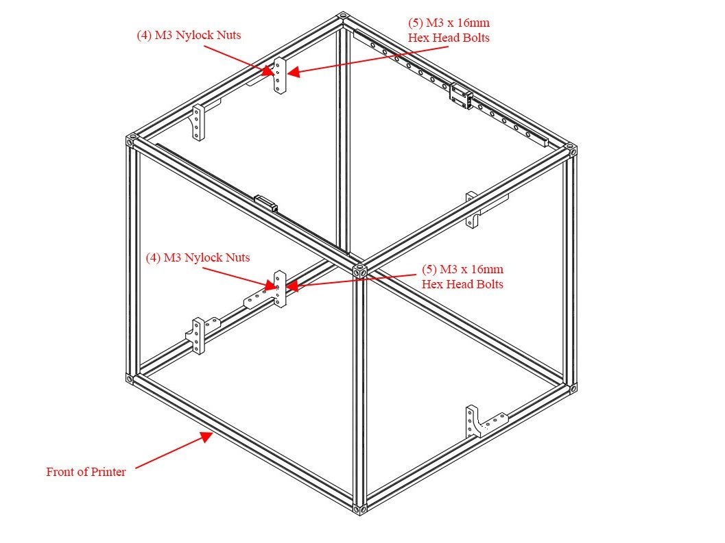
Step 3 — Add Bolts to Z Brackets

  • Put a M3 x 16mm hex head bolt through each Z Bracket and attach it loosely with an M3 nylock nut. Only thread the nut on loosely. Each bracket gets (4) M3 x 16mm hex head bolts with (4) M3 nylock nuts.
  • Repeat this process for all (6) Z brackets.

Step 4 — Prep Z Linear Rails

  • Prep the Z axis MGN12 linear rails in the same fashion as the X axis rails. There are additional hex head bolts in the ZLT supplement bag. These can be merged in with the rest of your hardware.
  • Select 4 evenly spaced holes in the rail. Place a lock washer on (1) M3 x 8mm Socket Head Cap Screw, and place it into the rail. Loosely thread on (1) M3 nut to the bolt.
  • Caution For the ZLT you should use (8) bolts spaced evenly, instead of (4) per rail. Extra 8mm bolts are located in the ZLT supplemental hardware bag.
  • Repeat for all (3) Z linear rails.
  • Caution It is highly recommended to use a bit of masking tape to keep the carriage from sliding off of the linear rail.

Step 5 — Install Z Linear Rails on Z Extrusions

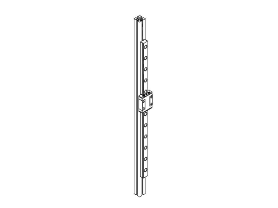
  • Slide the linear rails onto the (3) 445mm Z extrusions, and snug up the bolts (do not overtighten them.
  • The rail should sit ~20mm up from the bottom of the extrusion.
  • Caution It is highly recommended to use a bit of masking tape to keep the carriage from sliding off of the linear rail.

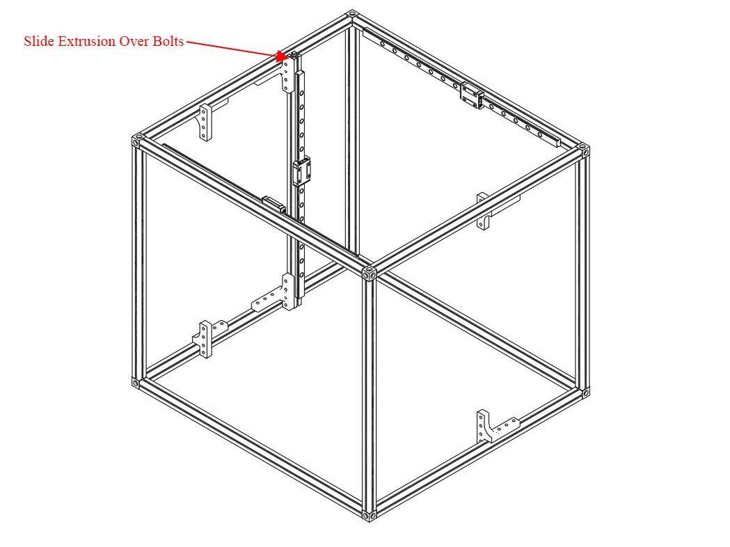
Step 6 — Install Z Extrusion Assemblies on Z Brackets

  • Take your Z extrusion with a linear rail attached, and slide it down onto the hex head bolts you added earlier on the Z brackets.
  • The extrusion should attach to all 4 bolts on both the top & bottom Z brackets.
  • Tighten down the nylock nuts to hold the Z extrusions in place.
  • Repeat for all (3) Z extrusions.

G) Sides Installation

It's assumed that you're building a kit from Filastruder, and you've completed all previous sections. At the end of this section you should have all your panels attached to your frame assembly.

Step 1

  • Prior to installing the side and bottom panels, deburr each panel along each edge to avoid injury.
  • It's important that you know which side is which on your frame, so the panels are installed correctly. If you haven't done so, mark the frame with tape, or write on the extrusions to note the front & top, at the least.

Step 2 — Bottom Panel Installation

  • Note When first installing the panels, only snug up the nuts, do not overly tighten them.
  • Flip the printer frame upside down, to install the bottom panel first.
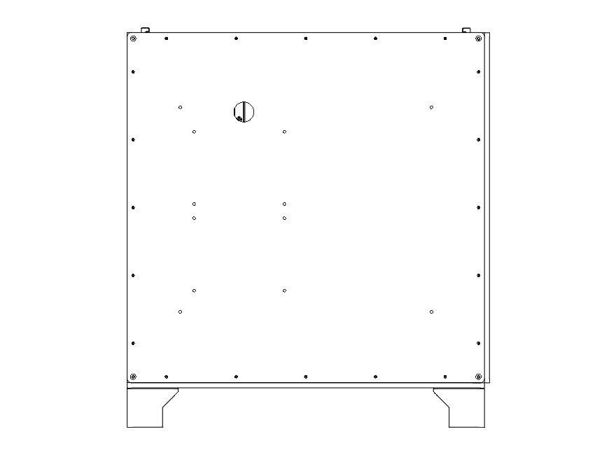
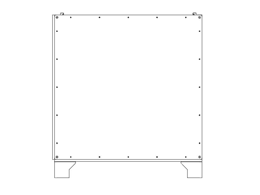
  • It's important the two holes are on the same side as the two Z towers (left side), and the "shiny" side of the panel faces out. The holes should be offset towards the front of the printer.
  • It's easiest to start by lining up the bolts close to where they'll need to be. Then start from one corner and work your way along the sides. Needle nose pliers can help to line the bolts up with the holes.
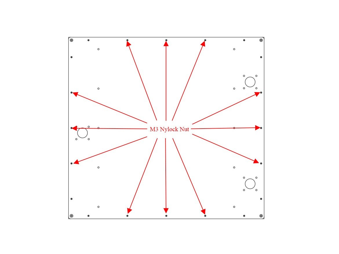
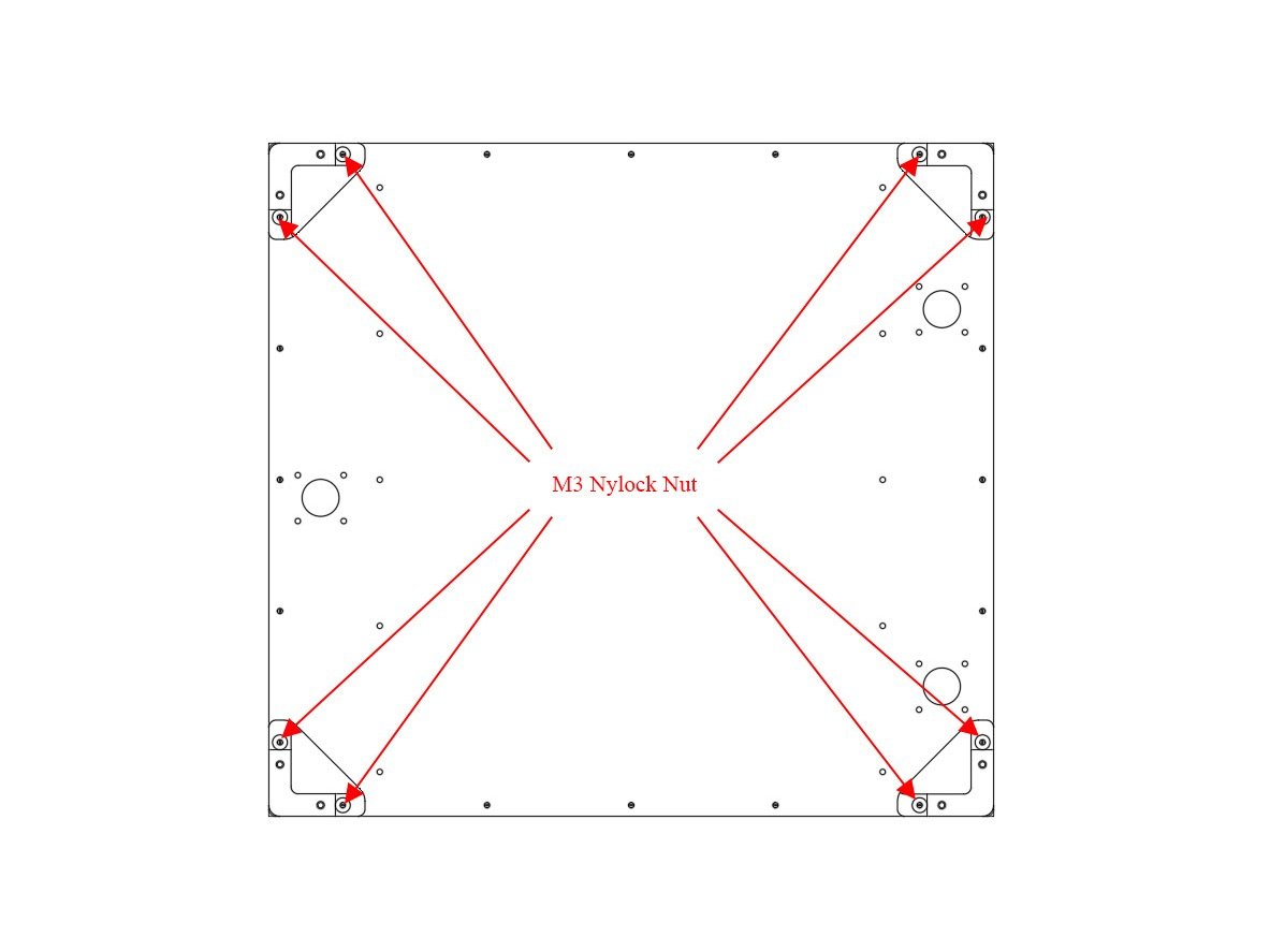
  • For the Feet, put them over the two bolts at each corner, and fasten each with (2) M3 Nylock Nuts. Do not overtighten them against the plastic.
  • Snug down the bottom panel using (3) M3 Nylock Nuts for the other bolts protruding along each side. A final tighten will be done later.

Step 3 — Back Panel Installation

  • Lay the printer front down on some blocks to protect the bolts.
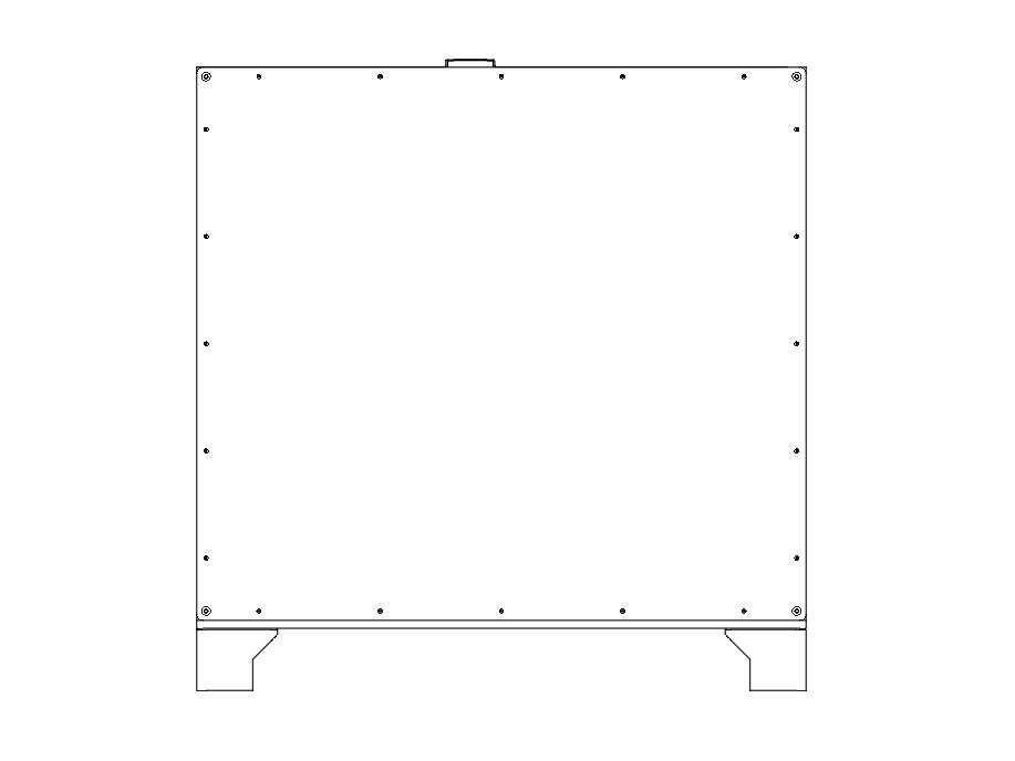
  • It's important that when looking down at the printer as in the picture, the two Z towers are on the Right side of the image.
  • The "textured" side of the HDPE panel should face out, shiny side in.
  • Install the back panel using (20) M3 Nylock Nuts, in the same method as before. Do not fully tighten the nuts yet.
  • Caution For the ZLT you'll need (24) M3 Nylock Nuts total.

Step 4 — Left Panel Installation

  • Lay the printer Right side down on some blocks to protect the bolts.
  • It's important that this panel goes on the left end of the printer, which is the end with two Z towers.
  • The "textured" side of the HDPE panel should face out, shiny side in.
  • Install the left panel using (20) M3 Nylock Nuts, in the same method as before. Do not fully tighten the nuts yet.
  • Caution For the ZLT you'll need (24) M3 Nylock Nuts total.

Step 5 — Right Panel Installation

  • Lay the printer left side down on some blocks.
  • It's important that this panel goes on the side with the single Z tower. Note the position of the hole for the cables to pass through.
  • The "textured" side of the HDPE panel should face out, shiny side in.
  • Install the Right panel using (20) M3 Nylock Nuts, in the same method as before. Do not fully tighten the nuts yet.
  • Caution For the ZLT you'll need (24) M3 Nylock Nuts total.

Step 6 — Front Panel Installation

  • Lay the printer back side down.
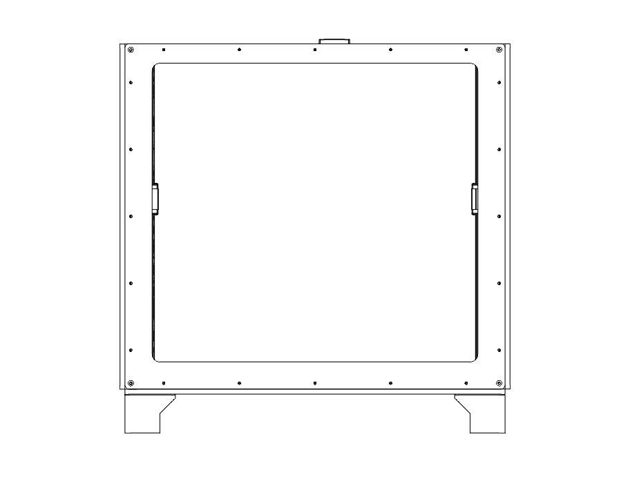
  • The "textured" side of the front HDPE panel should face out, shiny side in.
  • The thinner edge of the front panel goes towards the top of the printer.
  • Install the front panel using (20) M3 Nylock Nuts, in the same method as before. Do not fully tighten the nuts yet.
  • Caution For the ZLT you'll need (24) M3 Nylock Nuts total.

Step 7 — Installing the optional Halo

  • If you have a Halo, now is the time to install it. Generally use (1) M3 x 10mm button head bolt bolt and (1) M3 washer per "slot" in the Halo.
  • Center the bolt in the middle slot, and put the bolts in the outside slots at the outside ends of the channels.
  • Be sure to roughly balance the number of M3 nuts between the bolts holding down the Halo.
  • The Stepper Mounts for the Halo go on the right side of the printer, idler mounts to the left.

Step 8 — Squaring your Frame

  • Now is when you want to square up your frame. Start with the bottom panel, and get it as centered and even as you can.
  • With the printer laying on its back. Tighten all 5 nuts (including the feet) along one side of the bottom panel. Use a square or 123 blocks to square up the bottom extrusions, and tighten down the rest of the nuts on the bottom panel.
  • Repeat this process for each of the side panels, tightening the bolts along the bottom of each panel first.
  • Caution Be sure the side panels do not protrude above the top extrusions before tightening them.

H) Leadscrews and Z Yokes

Step 1 — Z Stepper Installation

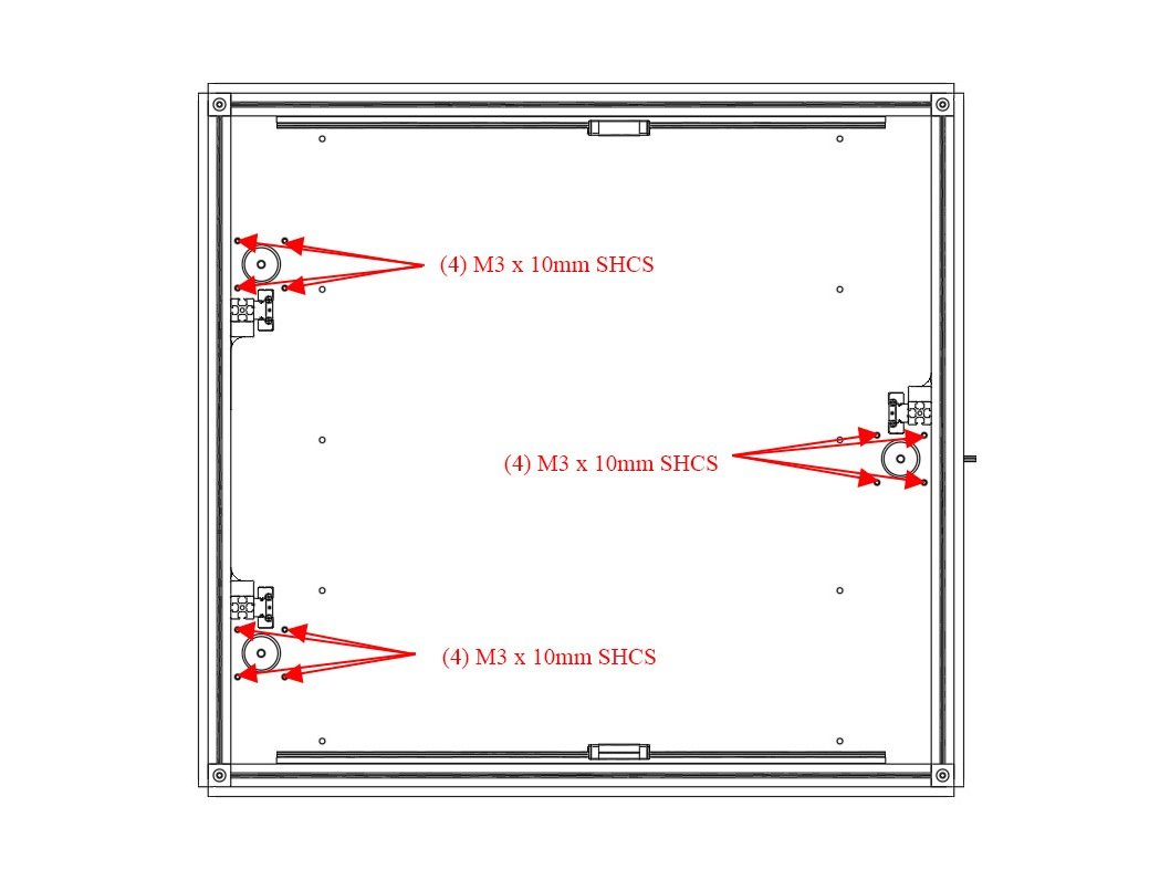
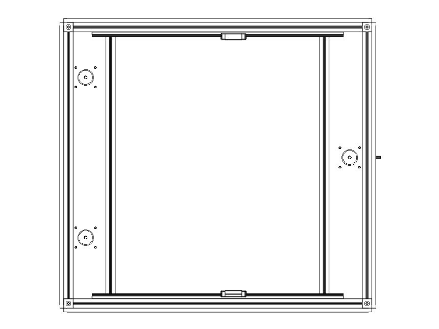
  • Install the (3) Z steppers into the bottom panel using (4) M3 x 10mm socket cap head screw per stepper. The connectors should point towards the right side of the printer.
  • Caution It's important the Z towers are positioned on the correct side of the steppers, as is shown in the picture.

Step 2 — Bottom Brace Installation

  • Caution Skip this step if using an aluminum base plate
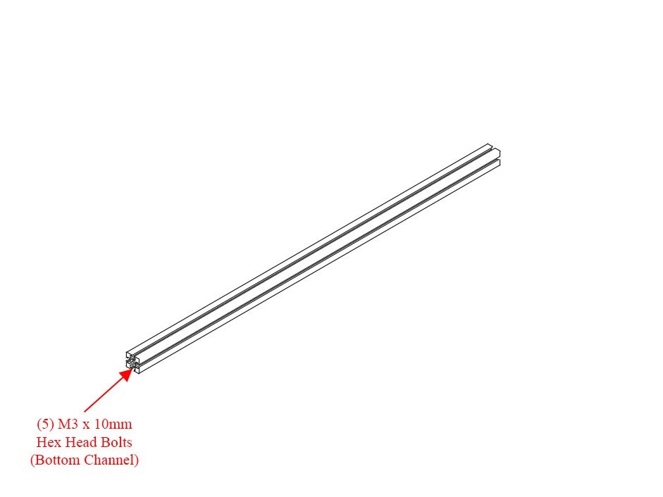
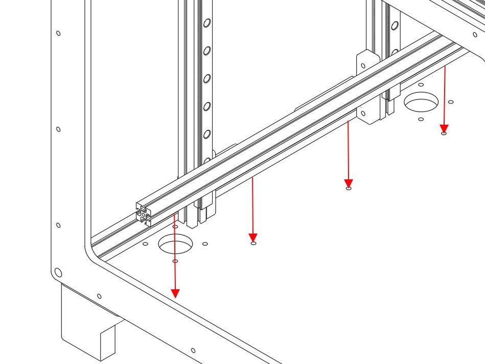
  • Insert (5) M3 x 10mm Hex Head Bolts into the bottom channel of one of the remaining 425mm Extrusions.
  • Lower the extrusion to the bottom panel so the bolts go through the 5 holes that go front to back in the panel, near the left side steppers.
  • Secure the bottom panel brace using (5) M3 washers and (5) M3 nuts on the bottom side of the printer.
  • Repeat this process for the brace on the right side of the bottom panel.

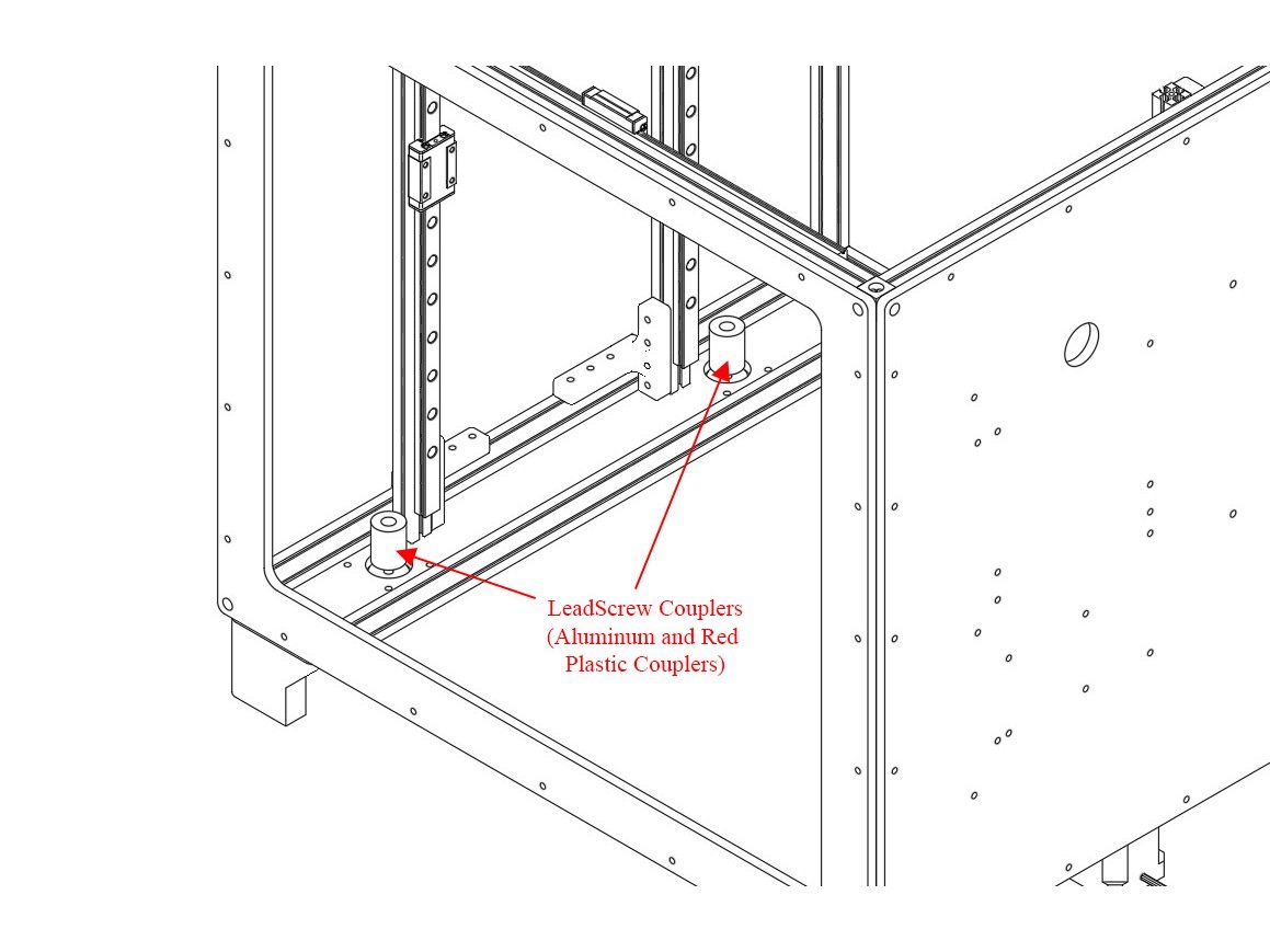
Step 3 — Leadscrew Couplers

  • Install the (3) Leadscrew couplers onto the Z stepper shafts. The couplers should be fully seated and tightened.
  • The Couplers are silver, with colored plastic combining the two halves.
  • Note The third stepper on the right side of the printer is not pictured.

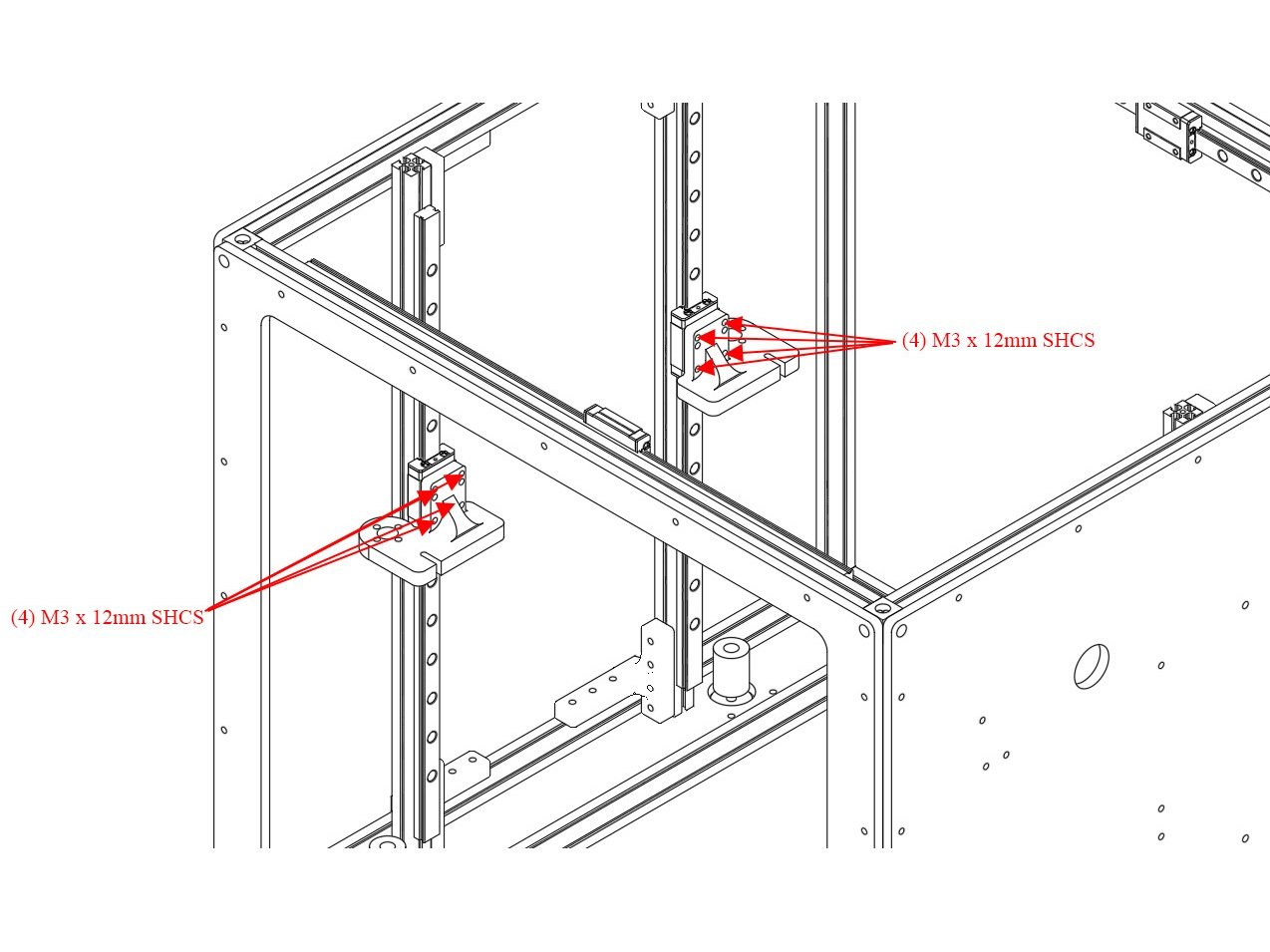
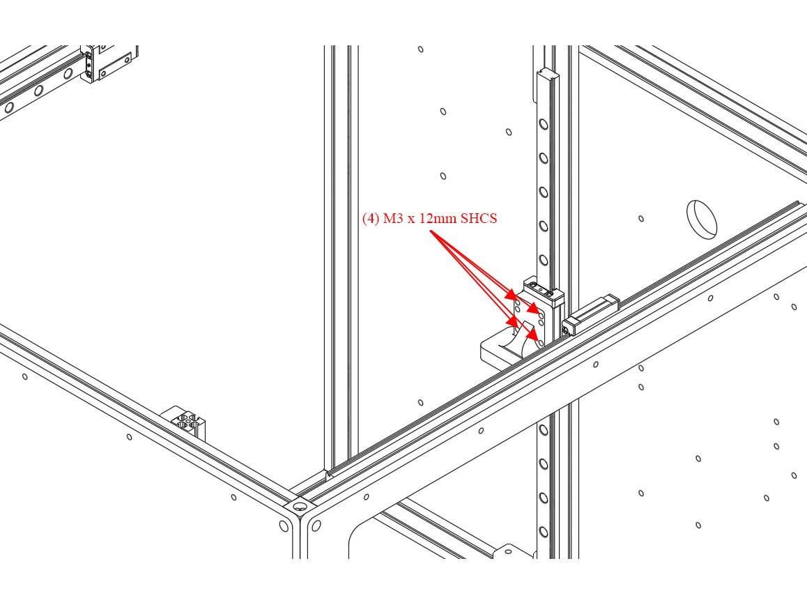
Step 4 — Yokes

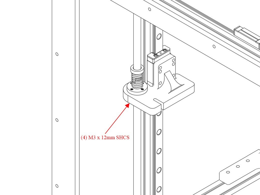
  • Install the (3) Z Yokes onto the Z carriages using (4) M3 x 12mm Button Head Bolts each. Note the orientation of the yokes in the pictures - ensure the hole for the leadscrew lines up over the stepper.
  • Caution For Misumi linear rails, use M3 x 10mm instead of M3 x 12mm bolts.

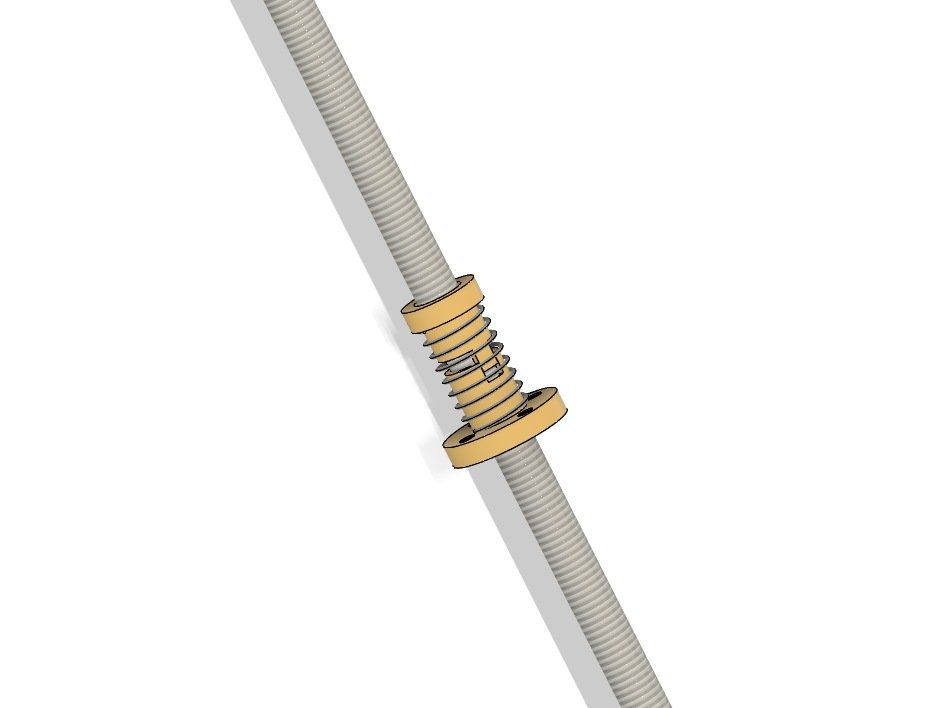
Step 5 — Anti-backlash Nut

  • Prepare the anti-backlash nut for mounting onto the leadscrew.
  • Thread the bottom half (with the flange) down onto the screw until just the teeth are sticking up past the end of the leadscrew.
  • Put the spring on the bottom of the leadscrew nut and hold it there until the next step.
  • Insert the top of the leadscrew nut, pushing down until the teeth in the upper and lower parts interlock.
  • Thread the nut assembly onto the leadscrew, until it's about 1/3 of the way down.
  • Repeat the above steps for the other (2) leadscrews.

Step 6 — Leadscrews

  • Insert the leadscrew down through the hole in the yoke, and into the leadscrew coupler.
  • Note You may need to slide the Z tower around to line it up so you can get the leadscrew into the coupler.
  • Tighten the grub screw in the coupler.
  • Insert (4) M3 x 12mm Button head bolts through the bottom of the yokes, and into the holes on the leadscrew nut flange. Do not overtighten, you can strip the Delrin.

I) Y Rail Installation

Step 1

  • Caution Newer Filastruder kits use Socket Cap Head Screws, use them in place of all button head screws in this section.

Step 2 — Front X Carriage Idler Installation

  • To prep for the Y rail installation we need to assemble the X carriages and idlers. Locate the X carriage labelled as the "Front".
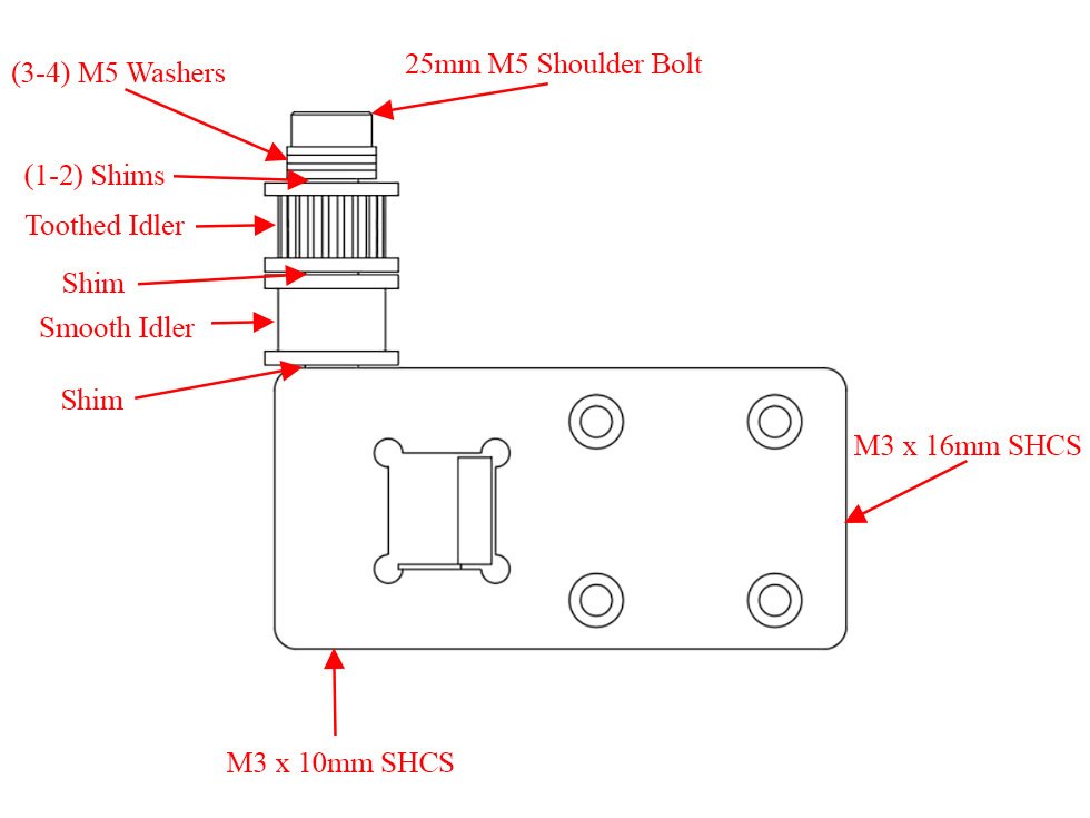
  • Insert an M3 x 10mm Button head bolt into the bottom of the X Carriage, and an M3 x 16mm button head bolt into the long horizontal hole in the X carriage, until they're flush with the inside edge.
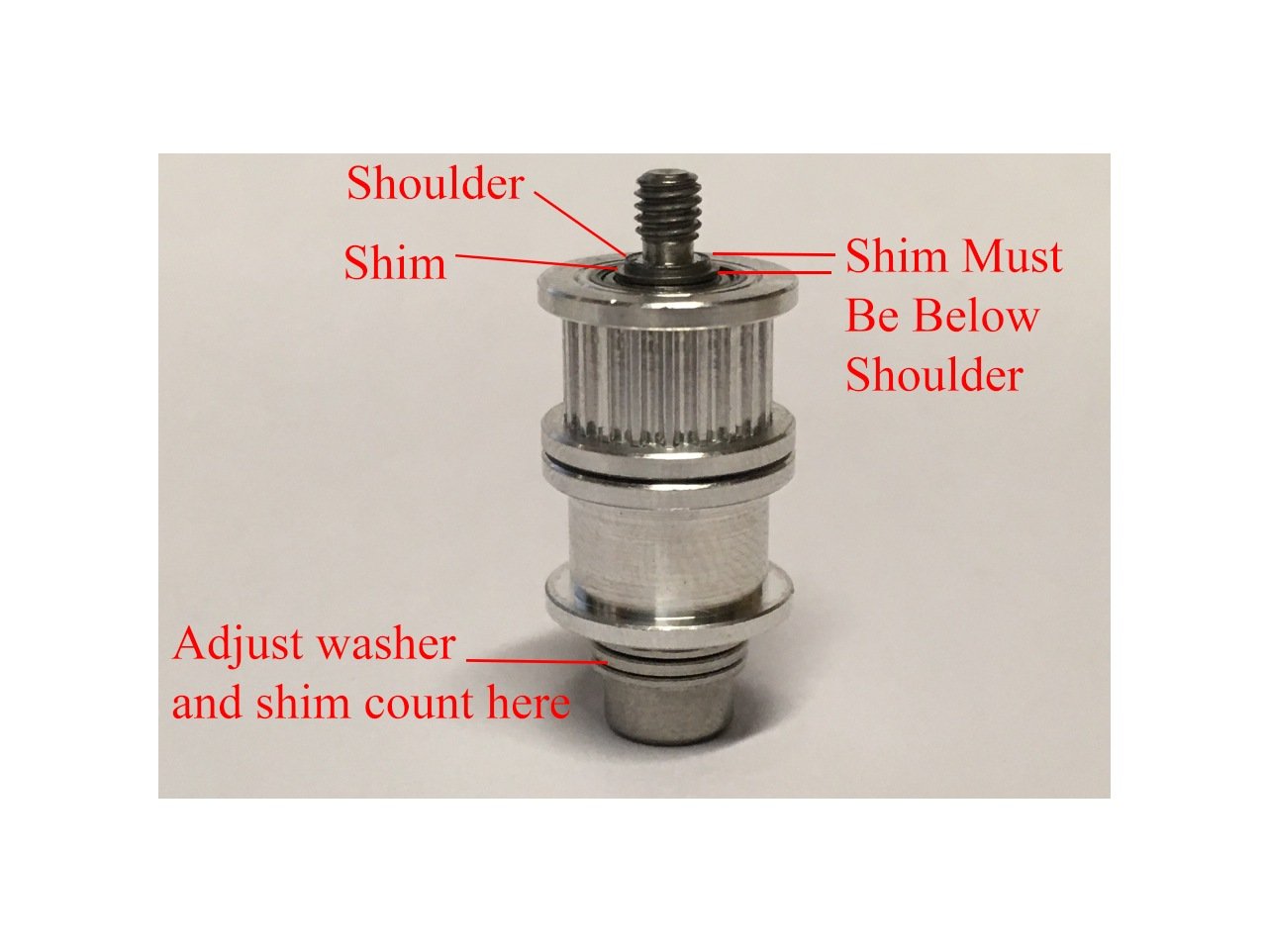
  • Begin by holding the shoulder bolt so the threads are pointed up. Place (3) M5 washers on the bolt, followed by (1) M5 shim. Next put on a toothed idler. Then another M5 shim, then a smooth idler, followed by a final M5 Shim.
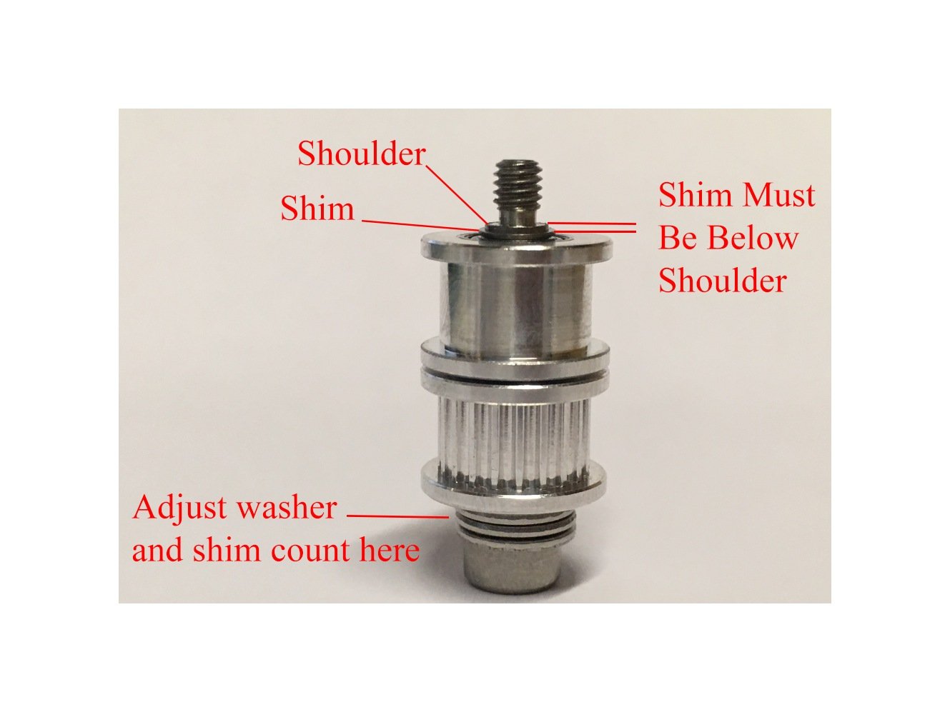
  • Visually look to see that the final shim is very close to level with the "shoulder" of the bolt.
    • Note If there's a gap, see if it's best filled by a shim, or a washer. You want to place those before the first shim you put on.
    • Note If instead the shim sticks out past the shoulder, you may need to remove a washer and replace it with a shim.
  • Once the "stack" is level with the shoulder, thread it into the X carriage (I leave the shoulder bolt pointing up, and turn the X carriage down onto it, being careful not to cross-thread it).
  • Caution The shoulder must be tight against the X-Carriage, with as little vertical play as possible. If the idlers don't spin smoothly, it's too tight and you need to remove a washer or shim. THERE MUST ALWAYS BE A SHIM DIRECTLY AGAINST EACH SIDE OF THE IDLERS.

Step 3 — Back X Carriage Idler Installation

  • Locate the X carriage labelled as the "Back".
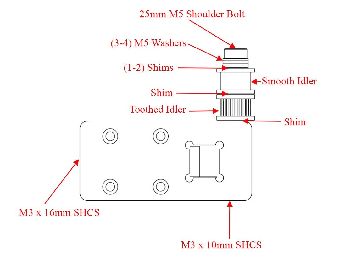
  • Insert an M3 x 10mm Button head bolt into the bottom of the X Carriage, and an M3 x 16mm bolt into the long horizontal hole in the X carriage, until they're flush with the inside edge.
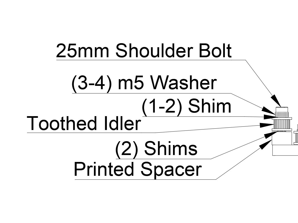
  • Begin by holding a 25mm shoulder bolt so the threads are pointed up. Place (3) M5 washers on the bolt, followed by (1) M5 shim. Next put on a smooth idler. Then another M5 shim, then a toothed idler, followed by a final M5 Shim.
  • Visually look to see that the final shim is very close to level with the "shoulder" of the bolt.
    • If there's a gap, see if it's best filled by a shim, or a washer. You want to place those before the first shim you put on.
    • If instead the shim sticks out past the shoulder, you may need to remove a washer and replace it with a shim.
  • Once the "stack" is level with the shoulder, thread it into the X carriage (I leave the shoulder bolt pointing up, and turn the X carriage down onto it, being careful not to cross-thread it). The shoulder must be tight against the X-Carriage, with as little vertical play as possible.
  • Caution The shoulder must be tight against the X-Carriage, with as little vertical play as possible. If the idlers don't spin smoothly, it's too tight and you need to remove a washer or shim. THERE MUST ALWAYS BE A SHIM DIRECTLY AGAINST EACH SIDE OF THE IDLERS.

Step 4 — Insert Y rail into X carriages

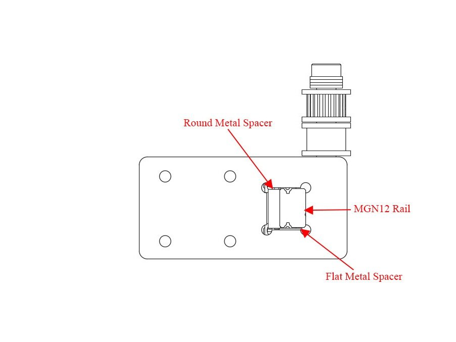
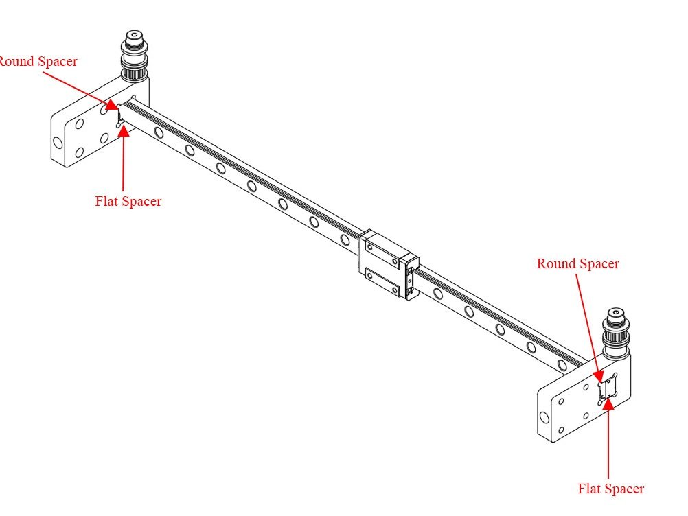
  • To insert the Y rail into the X carriages it gets oriented as in the image. Be sure the "inside' faces with the text milled into them face each other.
  • There is a round metal spacer that goes between the Y rail and the horizontal part of the carriage. Lightly tighten the horziontal M3 bolt t hold it in place.
  • There is a flat aluminum spacer that goes under the Y rail. Lightly tighten vertical bolt under the Rail against that spacer.

Step 5 — Bolt Y Rail Assembly onto X Rails

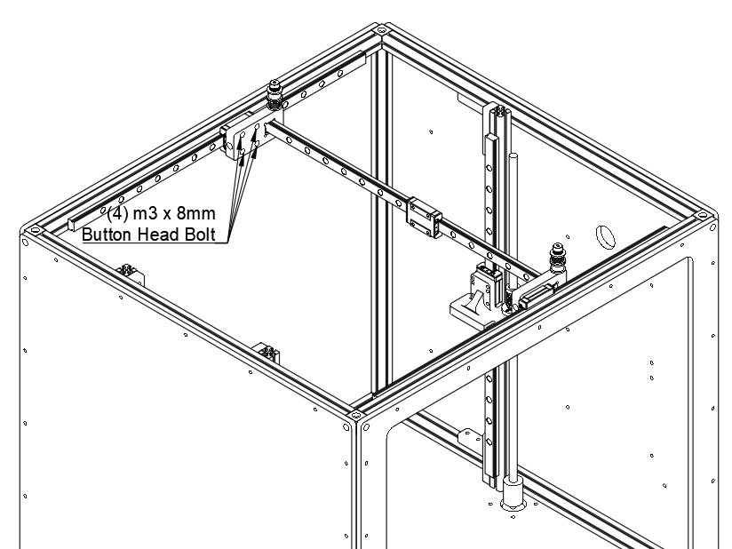
  • Attach the X carriages to the X rails using (4) M3 x 8mm Button head bolts each.

J) X/Y Steppers and Idlers

Step 1

  • Newer Filastruder kits use Socket Cap Head Screws, use them in place of all button head screws in this section.

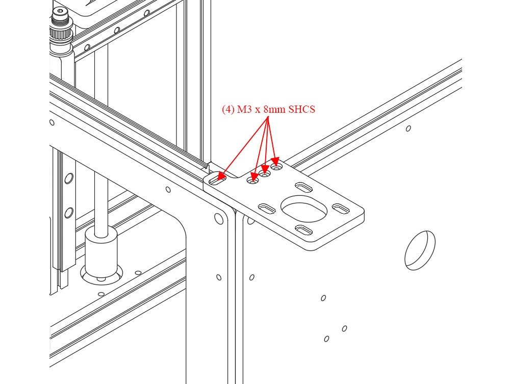
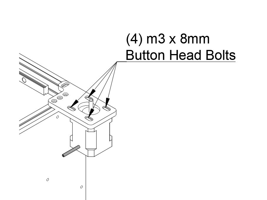
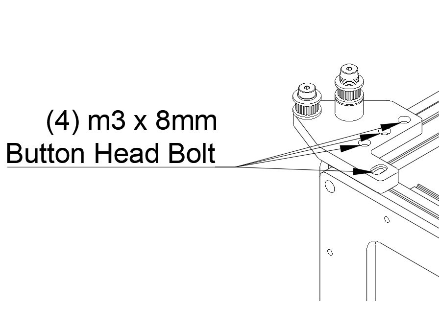
Step 2 — Front Stepper Mount

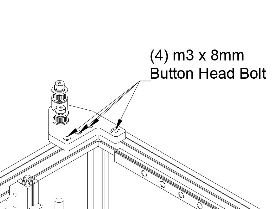
  • Attach the front stepper mount to the top of the frame using (4) m3 x 8mm button head bolts.
  • Note Don't overtighten them - you'll need to be able to adjust the position of the idler mount to align the belts later.

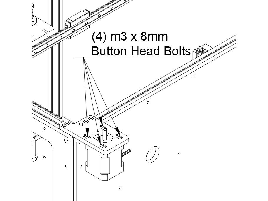
Step 3 — Install Front Stepper

  • Attach one of the 0.9 degree NEMA 17 steppers to the front idler mount using (4) m3 x 8mm Button Head Bolts.
  • The wiring connector should point towards the rear of the machine.

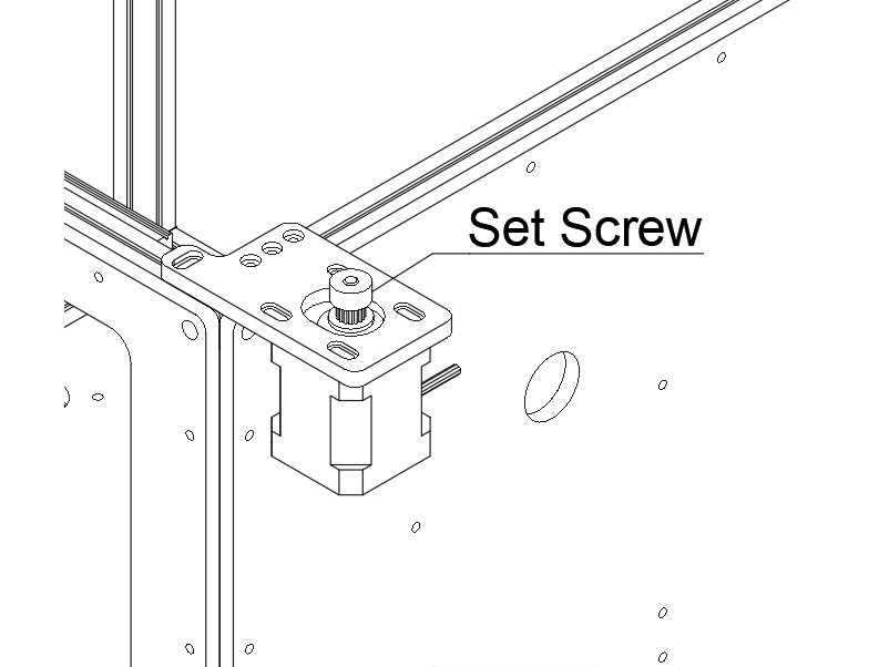
Step 4 — Install Front Pulley

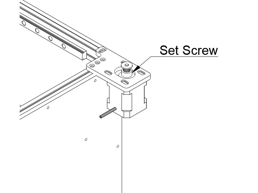
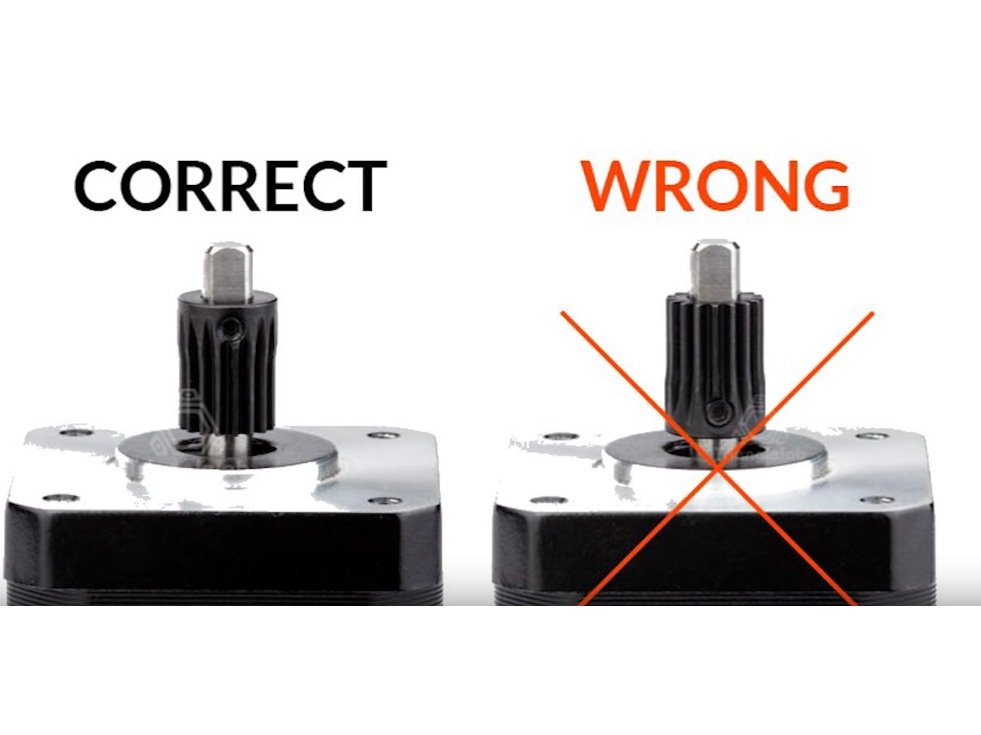
  • Install one of the 16t pulleys onto the stepper shaft with the teeth facing down. There are two set screws, be sure one of them is against the flat of the stepper shaft.
  • Note Don't overtighten the set screws, you'll need to adjust the pulley height to align the belt later

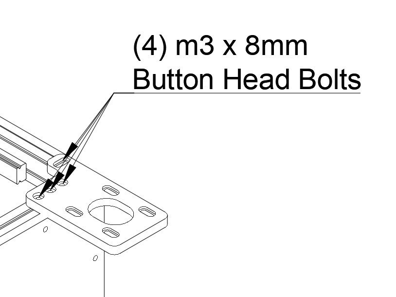
Step 5 — Rear Stepper Mount

  • Attach the rear stepper mount to the top of the frame using (4) m3 x 8mm button head bolts.
  • Note Don't overtighten them - you'll need to be able to adjust the position of the idler mount to align the belts later.

Step 6 — Install Rear Stepper

  • Attach one of the 0.9 degree NEMA 17 steppers to the front idler mount using (4) m3 x 8mm Button Head Bolts.

Step 7 — Install Rear Pulley

  • Install one of the 16t pulleys onto the stepper shaft with the teeth facing up. There are two set screws, be sure one of them is against the flat of the stepper shaft.
  • Note Don't overtighten the set screws, you'll need to adjust the pulley height to align the belt later

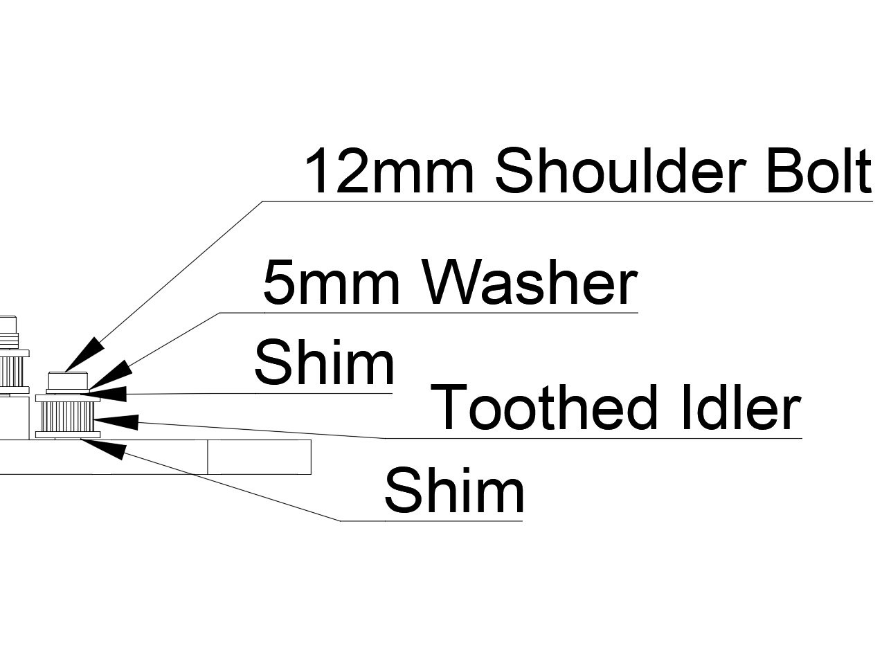
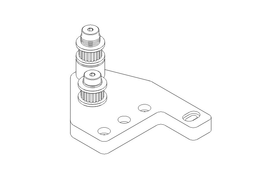
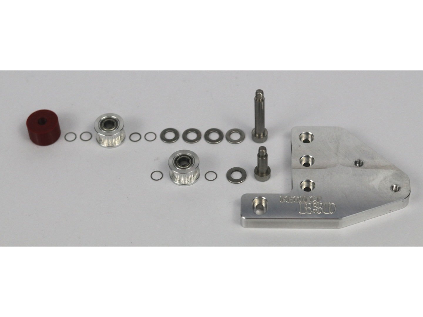
Step 8 — Install Idlers on Front Idler Mount (Diagrams)

  • Building the idler stacks is very similar to how the stacks were built for the Y carriage stacks.
  • Note There are photos to accompany this step in the next step.
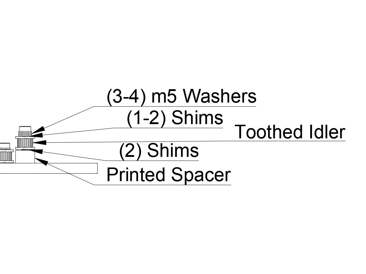
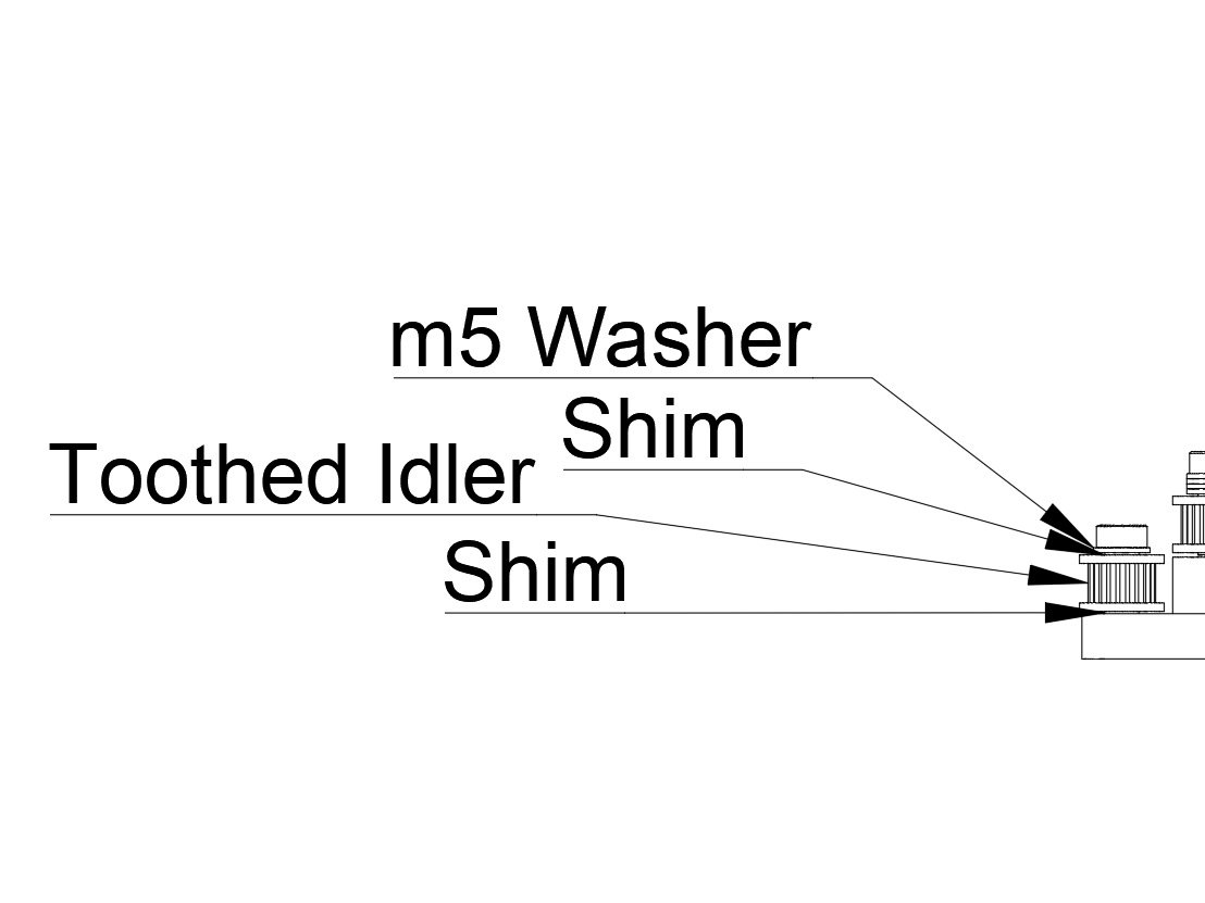
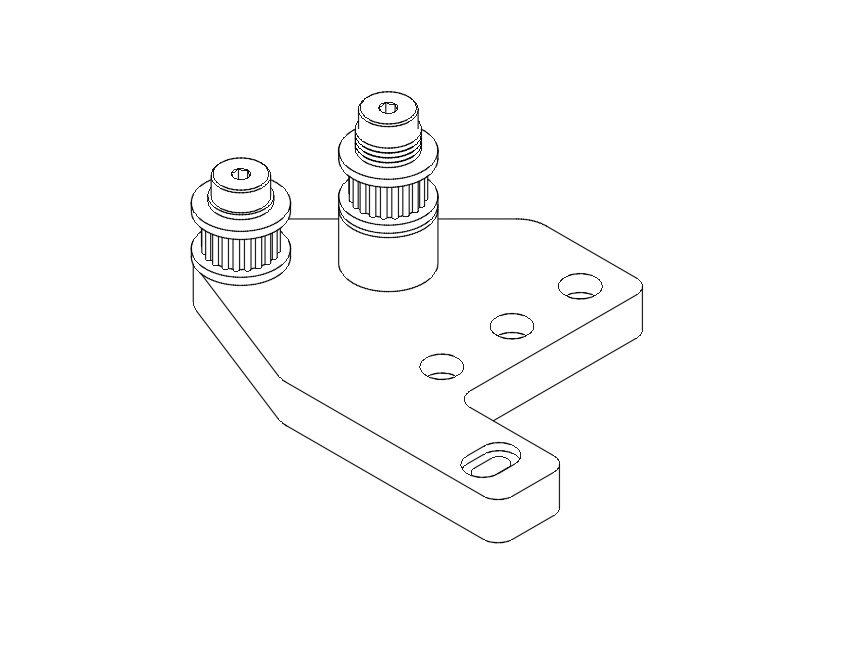
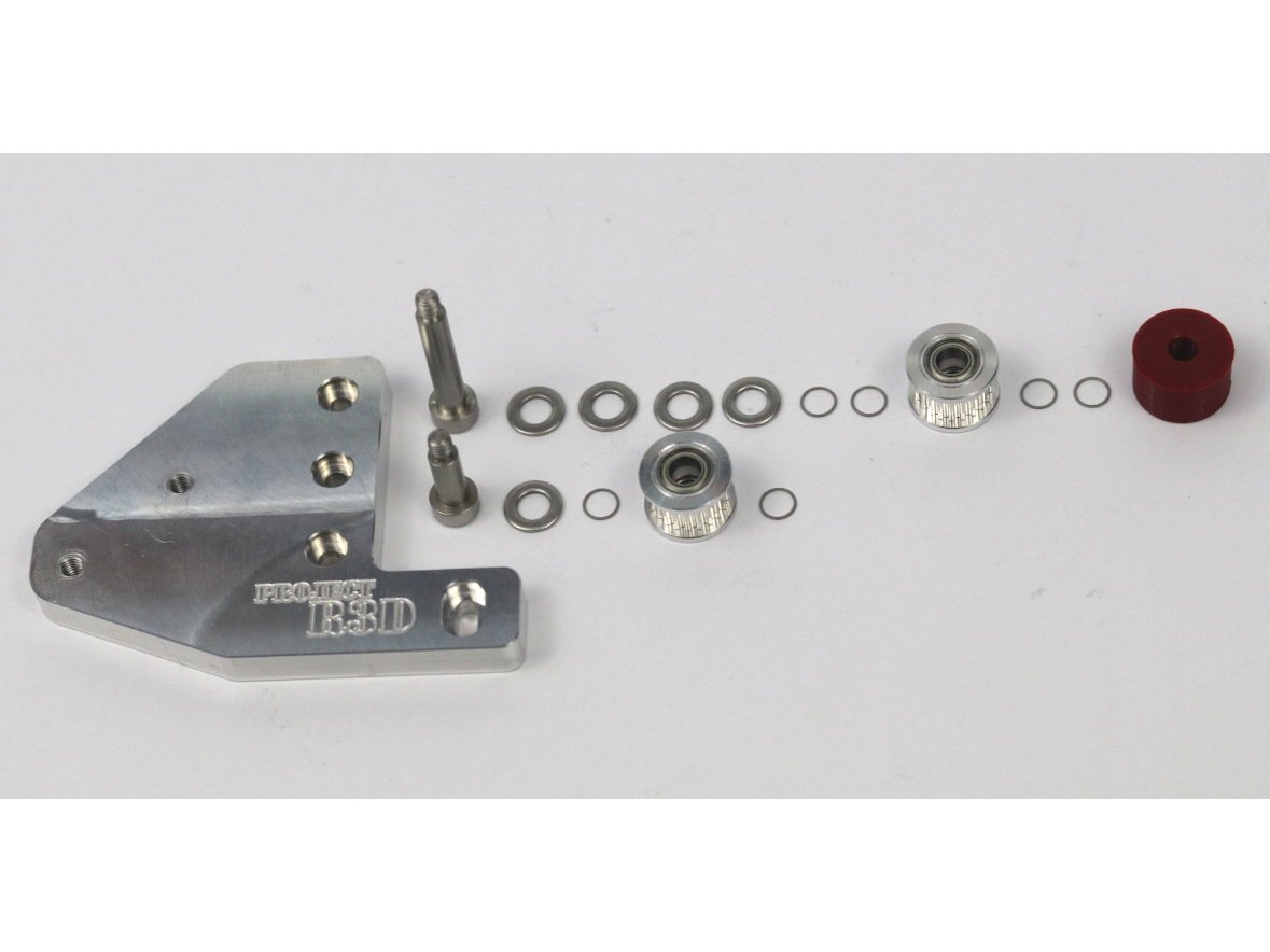
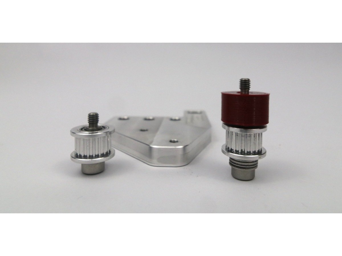
  • For the front idler, the stack for the outside bolt is the short stack. Turn a 12mm shoulder bolt upside down and install (1) M5 washer, then (1) M5 shim. Next add the 20T idler, then lastly (1) M5 shim.
  • Note You want to be sure the total stack is just slightly below the shoulder on the shoulder bolt. If there is room for another shim, take the last shim and pulley off, and put the extra shim on before the pulley.
  • Install the shorter idler stack in the outside hole on the idler mount.
  • For the front idler, the stack for the inside bolt is the tall stack. Turn a bolt upside down and install (3) M5 washers, then (1) M5 shim. Next add the 20T idler, then lastly (1) M5 shim.
  • Note You want to be sure the total stack is just slightly below the shoulder on the shoulder bolt. If there is room for another shim or washer, take the last shim and pulley off, and put the extra shim on before the pulley. If you can fit an extra washer, be sure to put it on before the first shim.
  • Install the taller idler stack in the inside hole on the idler mount.

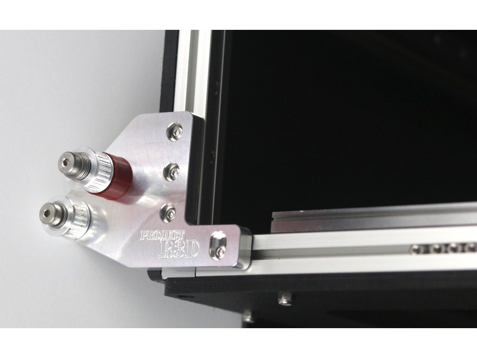
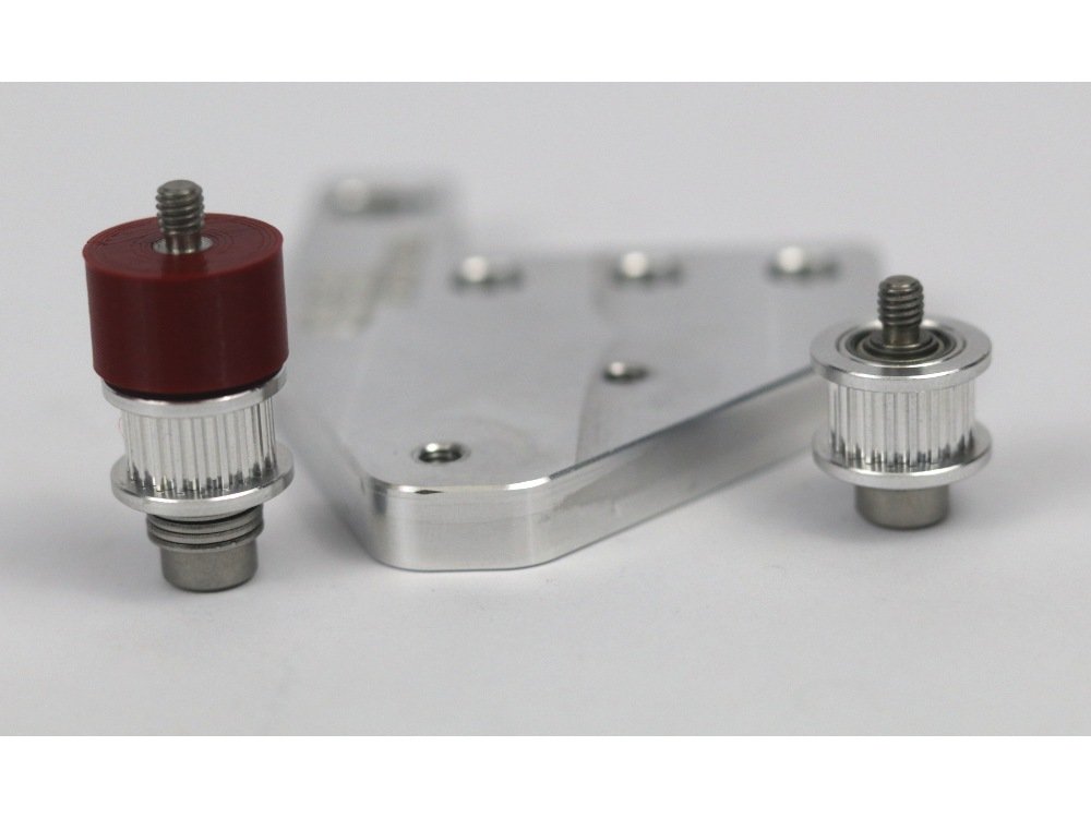
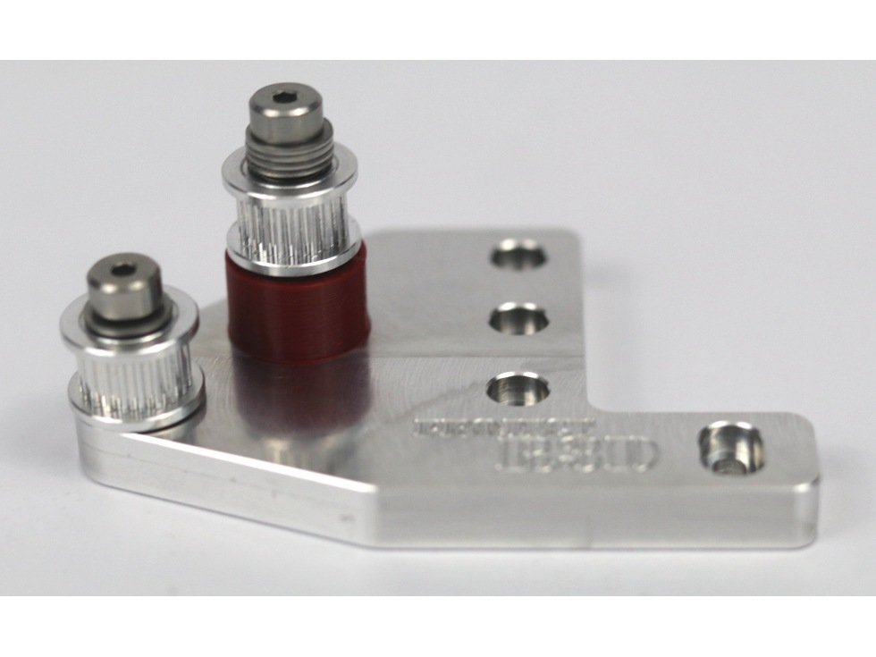
Step 9 — Install Idlers on Front Idler Mount (Pictures)

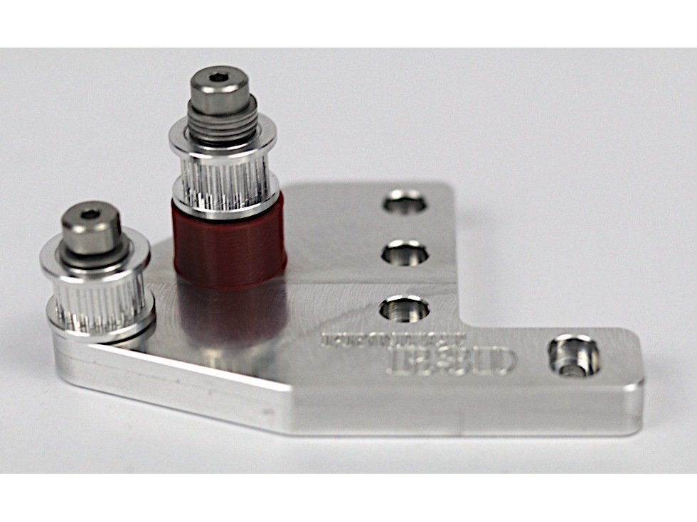
  • These photos can be used to validate the correct installation of the idler stacks on the front idler mount.

Step 10 — Install Front Idler Mount

  • Attach the front idler mount to the left side of the top of the frame using (4) m3 x 8mm button head bolts. Don't overtighten them - you'll need to be able to adjust the position of the idler mount to align the belts later.

Step 11 — Install Idlers on Rear Idler Mount (Diagrams)

  • There are photos to accompany this step in the next step.
  • For the rear idler, the stack for the inside bolt is the short stack. Turn a 12mm shoulder bolt upside down and install (1) M5 washer, then (1) M5 shim. Next add the 20T idler, then lastly (1) M5 shim.
  • You want to be sure the total stack is just slightly below the shoulder on the shoulder bolt. If there is room for another shim, take the last shim and pulley off, and put the extra shim on before the pulley.
  • Install the shorter idler stack in the inside hole on the idler mount.
  • For the rear idler, the stack for the inside bolt is the tall stack. Turn a bolt upside down and install (3) M5 washers, then (1) M5 shim. Next add the 20T idler, then lastly (1) M5 shim.
  • You want to be sure the total stack is just slightly below the shoulder on the shoulder bolt. If there is room for another shim or washer, take the last shim and pulley off, and put the extra shim on before the pulley. If you can fit an extra washer, be sure to put it on before the first shim.
  • Install the taller idler stack in the outside hole on the idler mount.

Step 12 — Install Idlers on Rear Idler Mount (Pictures)

  • These photos can be used to validate the correct installation of the idler stacks on the front idler mount.

Step 13 — Install Rear Idler Mount

  • Attach the rear idler mount to the rear left top of the frame using (4) m3 x 8mm button head bolts. Don't overtighten them - you'll need to be able to adjust the position of the idler mount to align the belts later.

K) Y Carriage

Step 1

  • Newer Filastruder kits use Socket Cap Head Screws, use them in place of all button head screws in this section unless noted.

Step 2 — Y Carriage Installation

  • Before you bolt the Y Carriage onto the Y rail, double check that all the brass inserts are in.
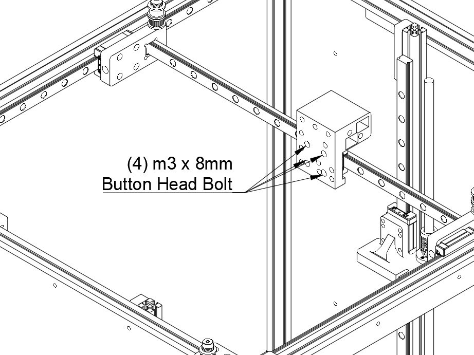
  • Bolt the Y Carriage to the Y rail using (4) m3 x 8mm button head bolts. (Socket Cap Head Screws will not work here, use Button Head regardless of the kit you're building) Make sure they're snug.
  • Note You may want a dab of loctite on the bolts for attaching the Y carriage to the Rail, they're hard to get to later.

Step 3 — Attach BLTouch to BLTouch Mount

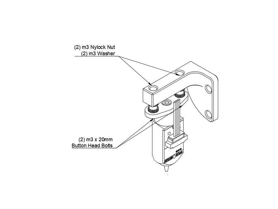
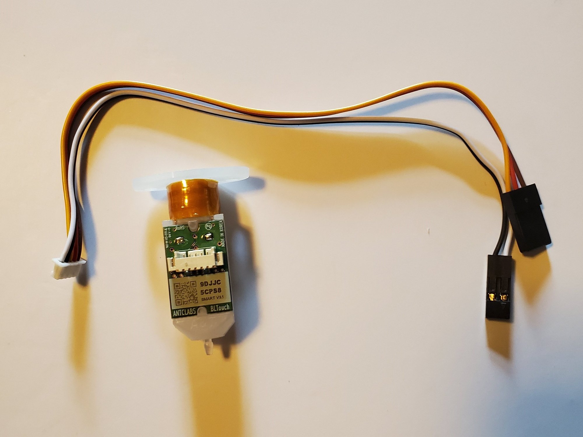
  • Remove the wiring that comes pre-installed on the bltouch by disconnecting the connector. The kit wiring harness has a connector, these wires are not needed.
  • Put (2) m3 x 20mm Button Head Bolts pointing up through the holes in the BLTouch.
  • Thread a brass insert down on the bolt, tight against the bltouch.
  • Pass the bolt up through the BLTouch mount
  • Put an m3 washer on the bolt, and then an m3 Nylock Nut.

Step 4 — Install BLTouch

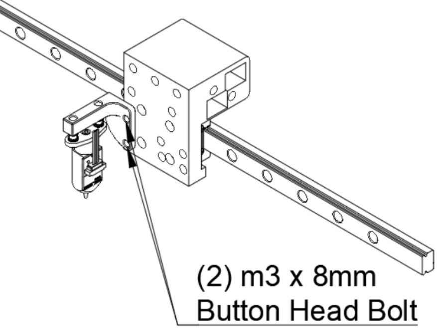
  • Attach the BLTouch mount to the lower left two holes in the Y carriage using (2) m3 x 8mm Button Head Bolts.

Step 5 — Prep Layer Fan Install

  • Locate the layer fan adapter (In this kits this part is white, not black as shown), and insert an M3 nut into the slot on it as shown.
  • Attach the layer fan to the bottom of your Y carriage using a single M3 x 6mm button head bolt. (Image is shown off of a printer for clarity)

Step 6 — Part Cooling Fan and Y Endstop Install

  • The Y endstop and part cooling fan share a cable harness, so we need to install them at the same time.
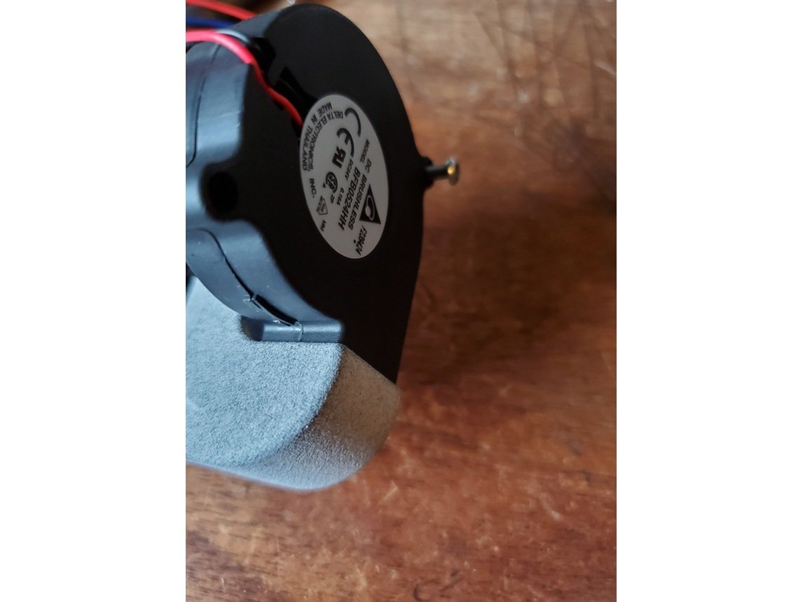
  • Attach the 5015 blower to the JT shroud using a 20mm Button Head Bolt.
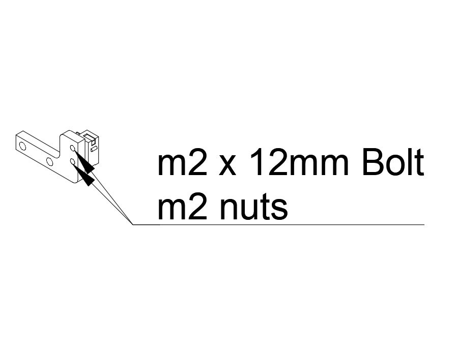
  • Attach the Y endstop switch to the Y endstop mount using (2) m2 x 12mm Bolts and (2) m2 nuts.

Step 7 — Attach Part Cooling Fan and Y Endstop

  • Start by attaching the Layer fan and shroud. Attach the Layer fan to the bottom of the adapter using one m3x8mm Button head bolt into the rear hole (the one going to the m3 washer) and one m3 x 12mm Button head bolt that will pass through the other hole and into the brass insert in the Y carriage.
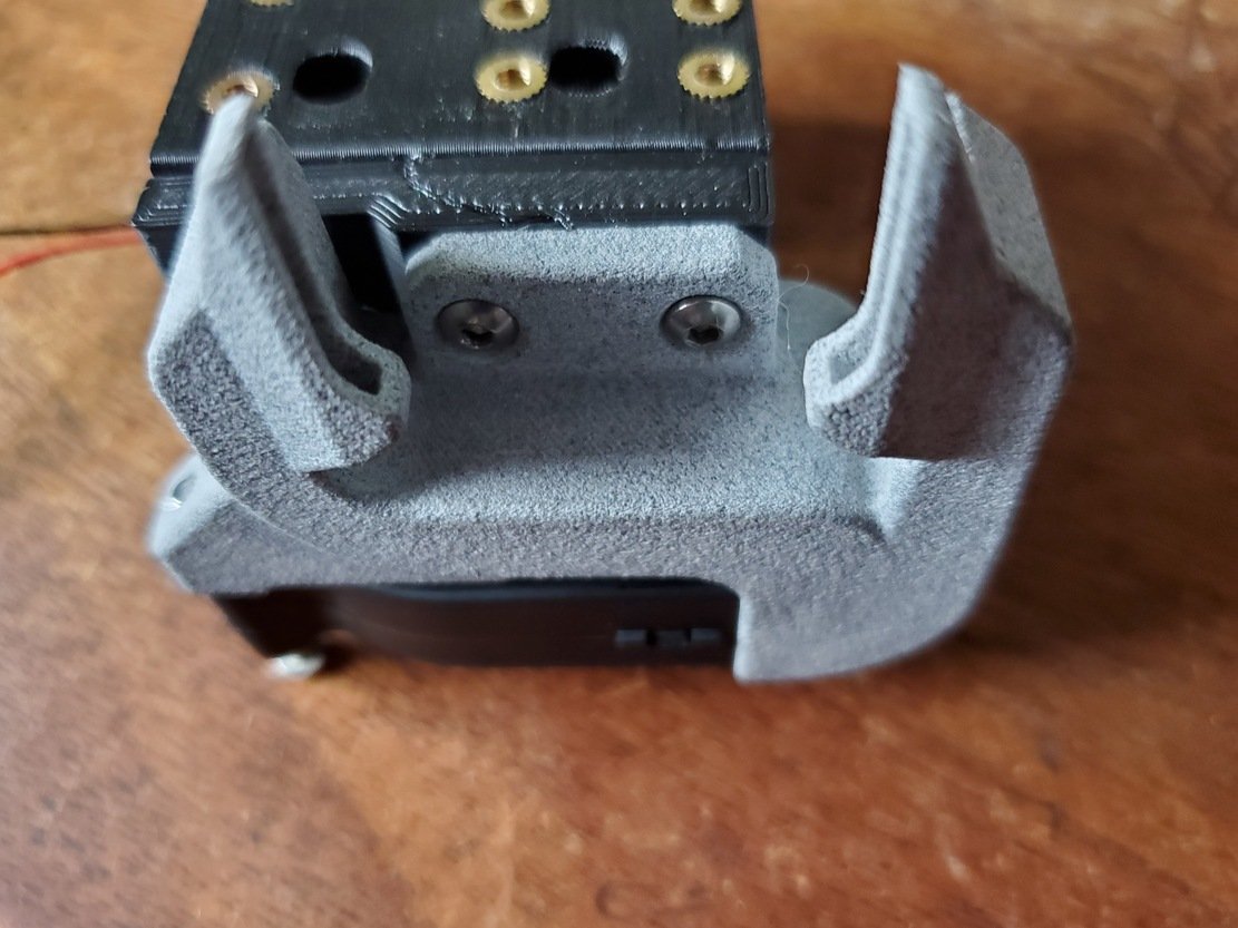
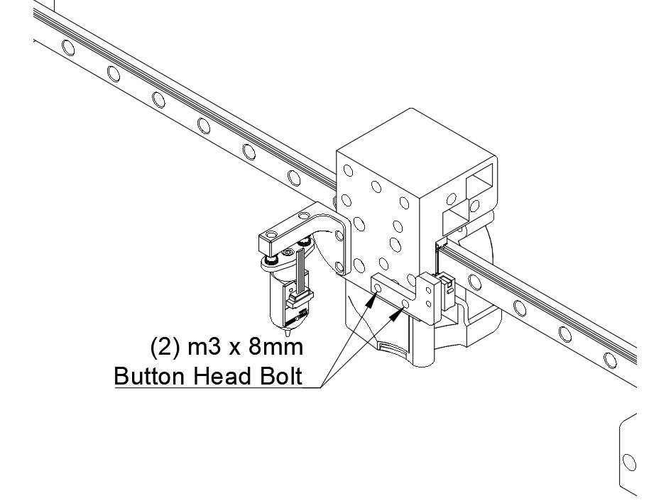
  • Attach the Y endstop mount to the bottom right two holes in the Y carriage using (2) m3 x 8mm Button Head Bolts

Step 8 — Prep Hotend Groove Mount

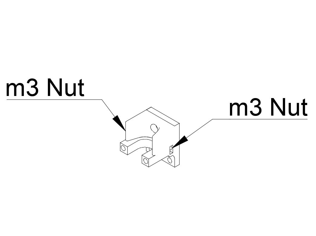
  • Insert one m3 nut into each side of the printed hotend mount. They can be hard to push in, using a screwdriver can help.
  • Note Push an allen wrench down through the bolt holes for attaching the hotend to center the M3 nuts, it will make threading a bolt in easier.

Step 9 — Hotend Mount Installation

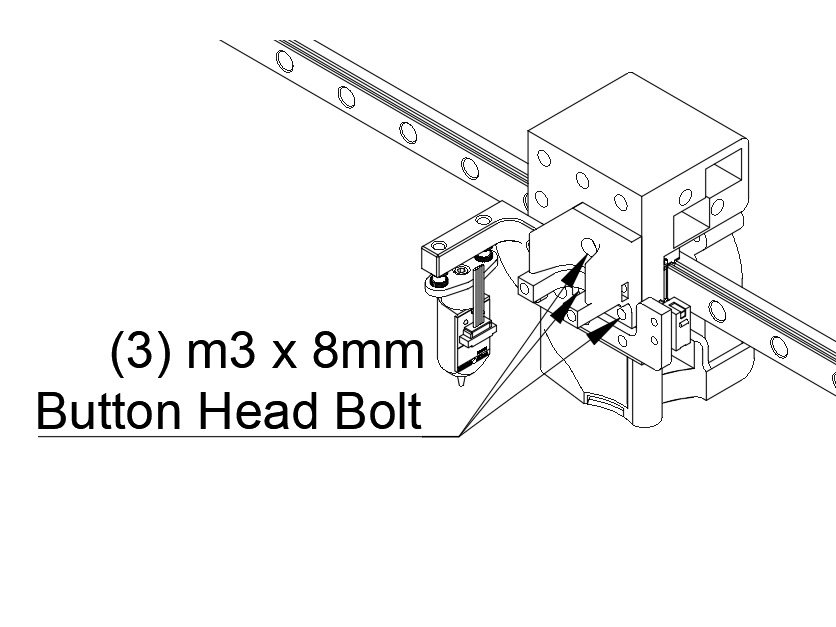
  • Attach the hotend mount to the Y carriage using (3) m3 x 8mm button head bolts. (Socket Cap Head Screws will not work for the bottom two, use Button Head regardless of the kit you're building)

Step 10 — BMG Mount Installation

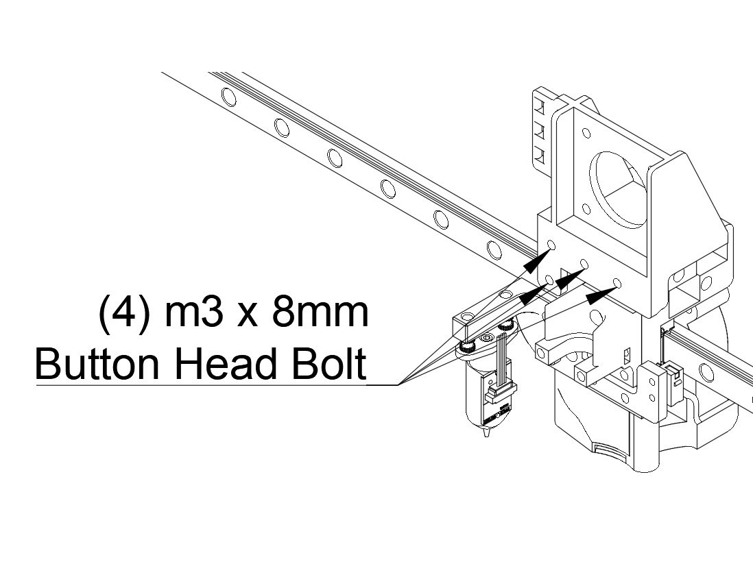
  • Attach the BMG mount to the hotend mount using (4) m3 x 8mm Button Head Bolts.

L) X/Y Belts

Step 1 — How to Install Belt Clips

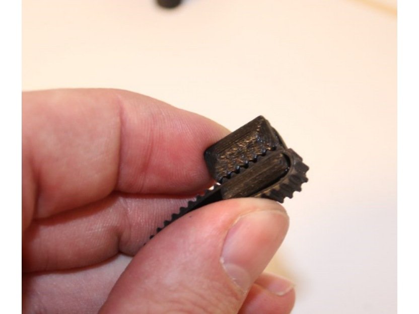
  • To install a belt into a belt clip, put the belt through the clip, and leave a bit of a tail - about an inch or so, to allow some adjustment later.

Step 2 — Y / Front Belt Installation

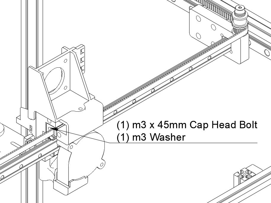
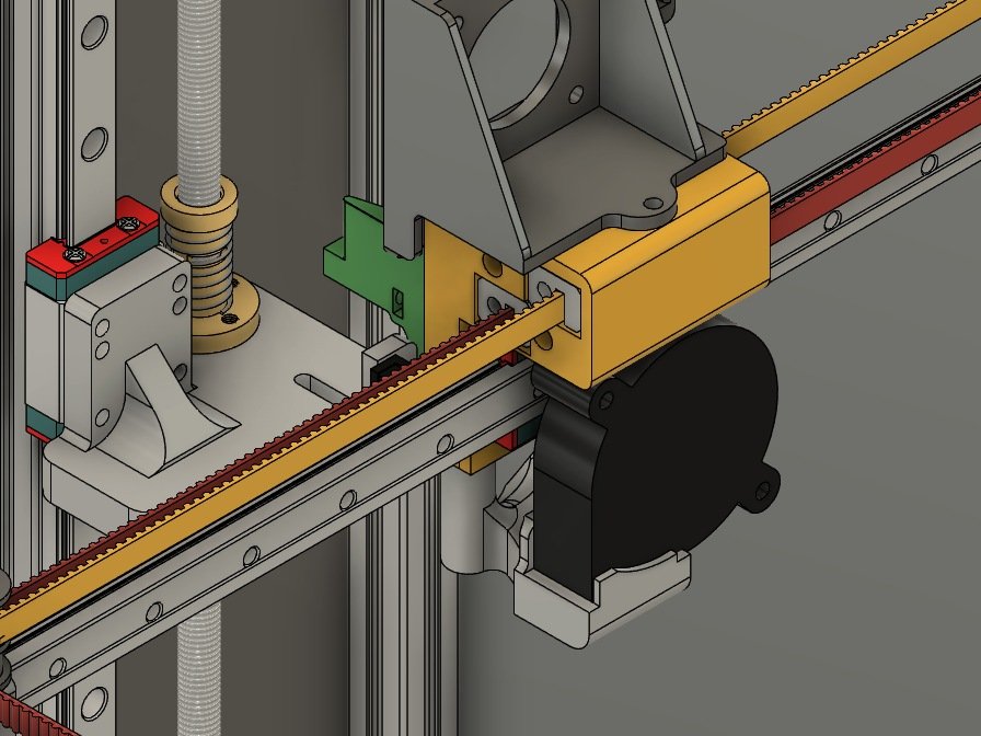
  • Start with the front or "Y" belt. Insert the clip with the belt on it into the lower left hole at the front of the Y carriage. Make sure the bolt hole lines up properly.
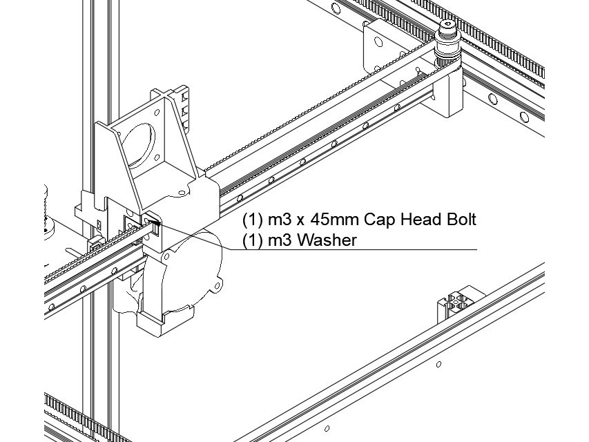
  • Attach the clip using (1) m3 x 45mm cap head bolt and (1) m3 washer.
  • Caution The Belt teeth should be facing the left of the printer.

Step 3 — Y Belt Installation Continued

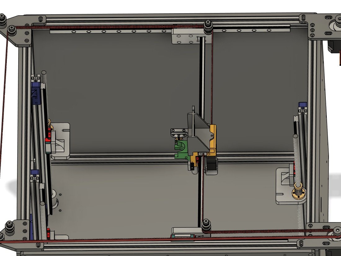
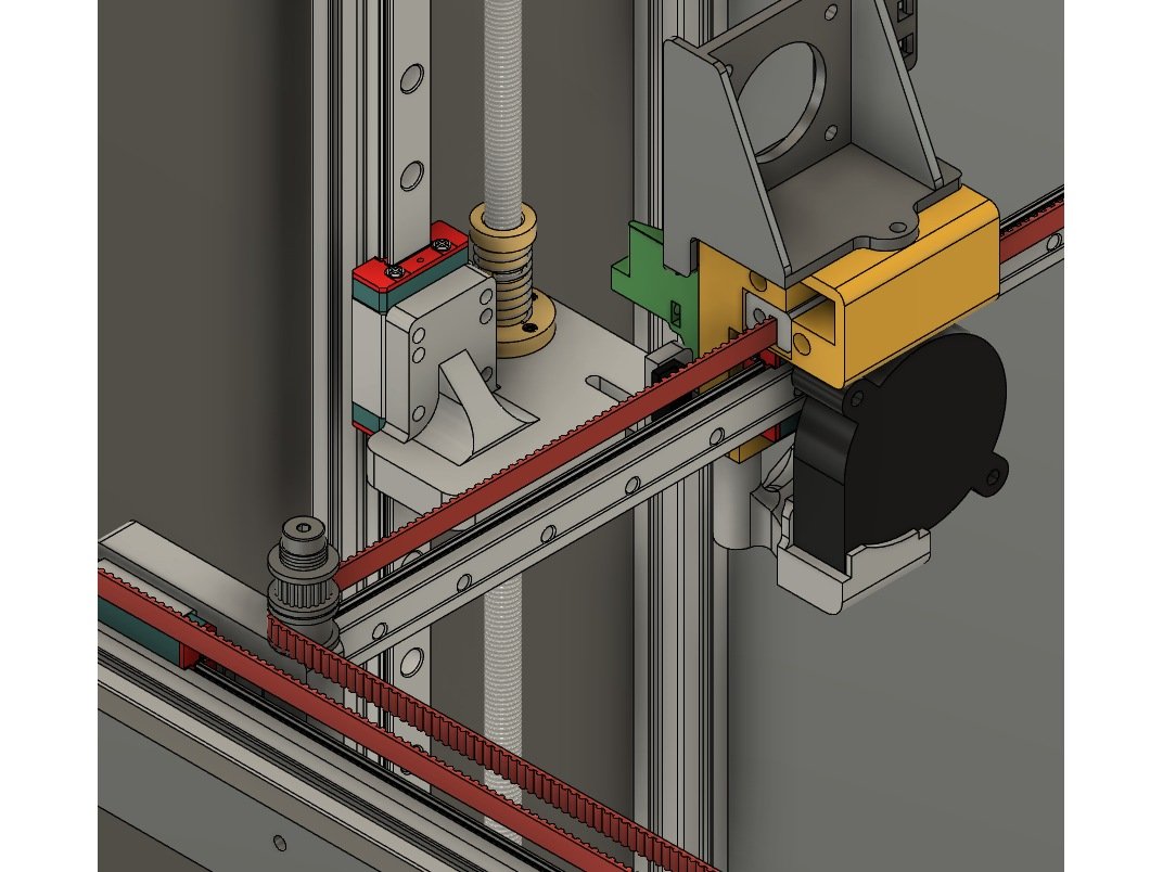
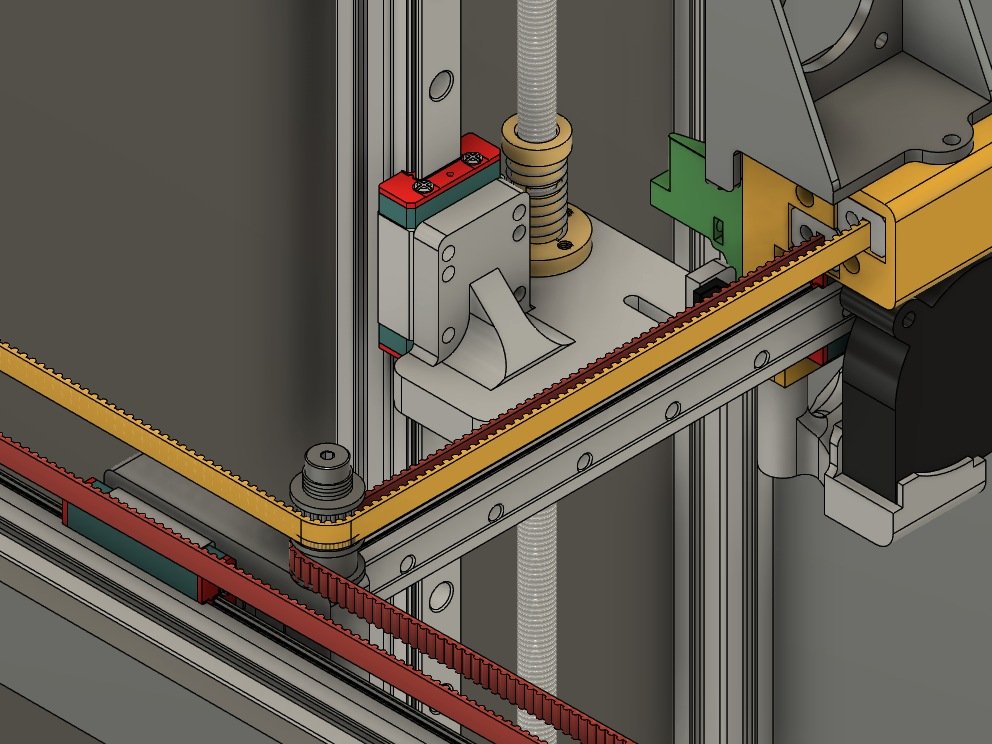
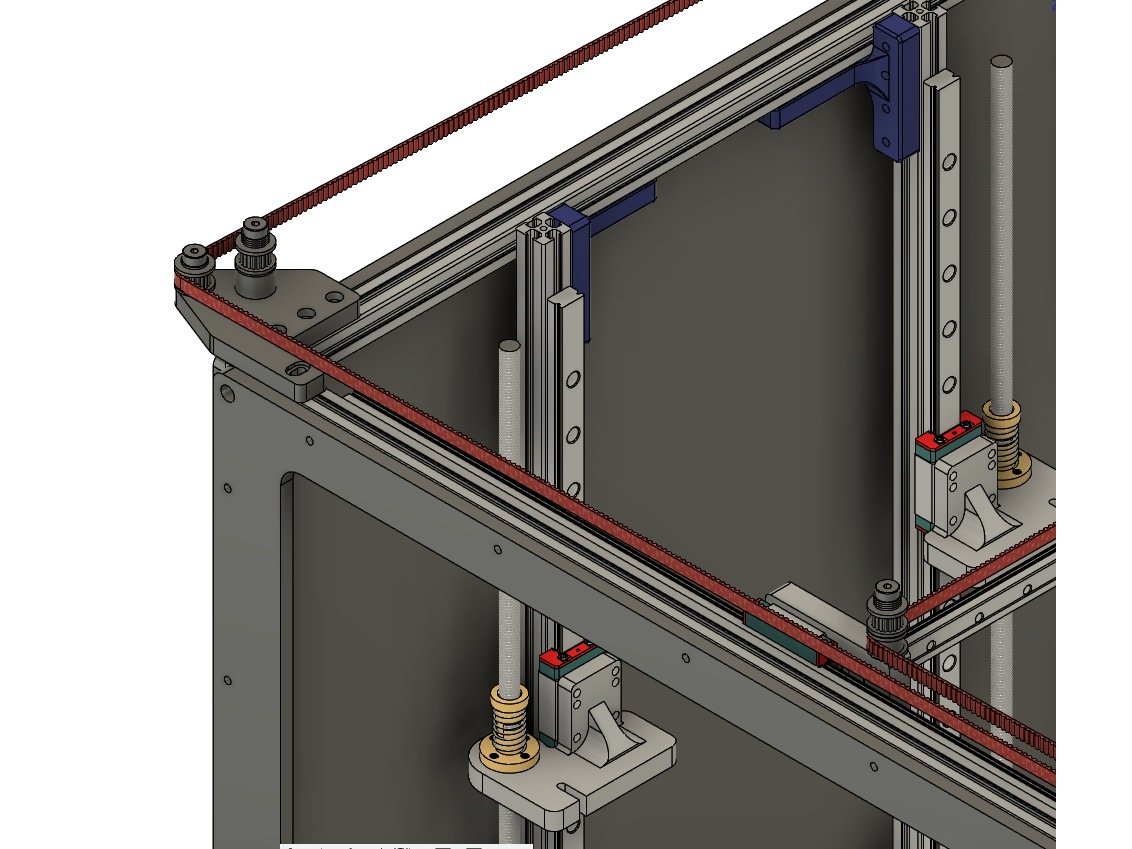
  • The belt (shown in red) should go from the Y carriage and then around the lower smooth idler on the front X carriage.
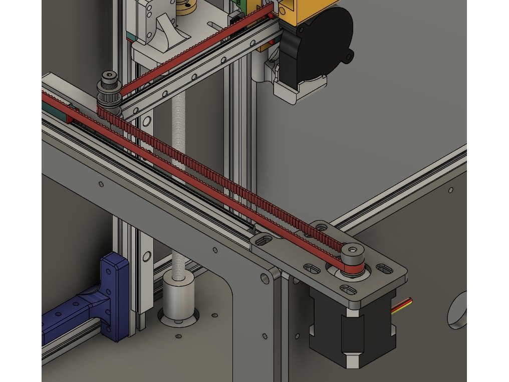
  • From the idler the belt should turn to the right and loop around the front stepper pulley.
  • Caution The teeth should engage the pulley.
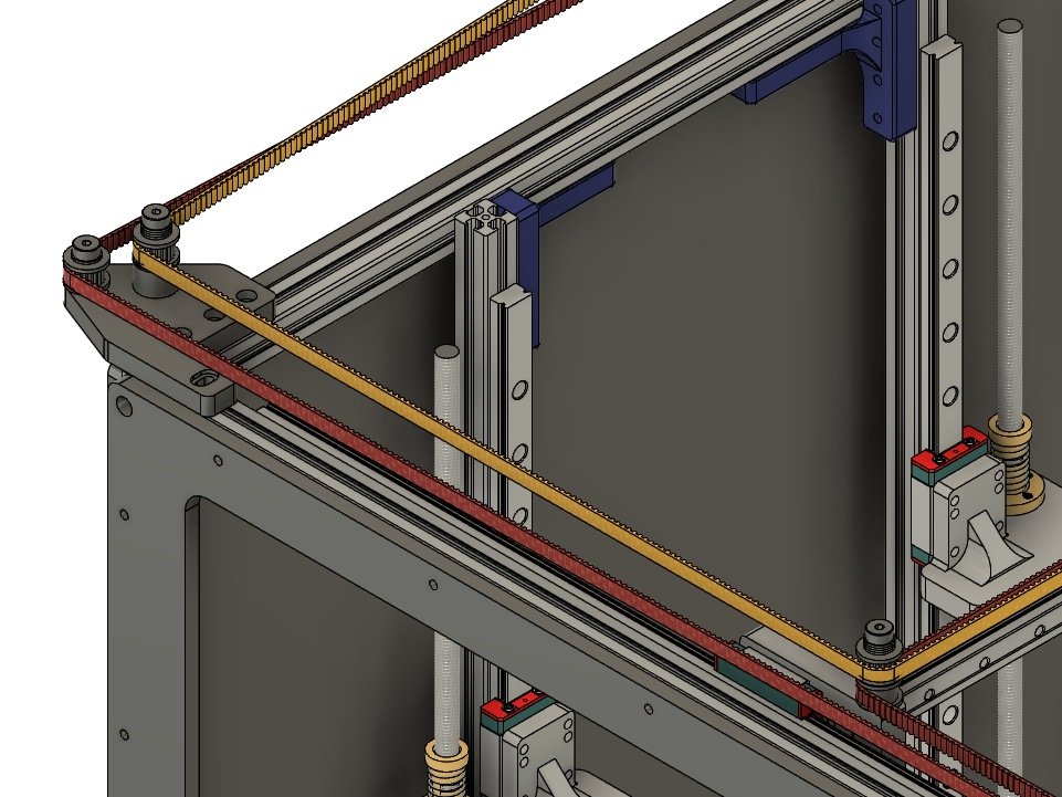
  • From the stepper the belt goes across the front of the printer and around the toothed idler on the outside, shorter shoulder bolt.

Step 4 — Finishing Y Belt Installation

  • The belt should cross to the left of the printer, and the teeth should engage the toothed idler on the shorter, inside shoulder bolt on the rear idler mount.
  • From there the belt should follow along the back of the printer, with the toothed side wrapping around the lower toothed idler on the X carriage.
  • Put another belt clip on, and insert the bolt into the lower rear hole on the Y carriage. Attach it with (1) m3 x 45mm bolt and (1) m3 washer.
  • Caution Be sure the belt is properly seated around the idlers and pulley, and not twisted along its length.
  • Don't worry about the belt being tight - we'll tension it later. For now "close" is good enough.
  • Cut the belt, leaving an approximately 1" tail in case you need to adjust it.

Step 5 — X / Rear Belt Installation

  • To install the rear or "X" belt, start by installing a belt clip on the end of the belt, and insert it into the top hole on the front of the Y carriage.
  • Attach the belt clip using (1) m3 x 45mm cap head bolt and (1) m3 washer.
  • Caution The belt teeth should be facing the left of the printer.

Step 6 — Y Belt Routing

  • To route the belt it should leave the Y carriage and wrap around the toothed idler at the top of the stay on the front X carriage.
  • From the X carriage the belt follows along the front of the printer to the toothed idler at the top of the tall stack on the front idler mount.

Step 7 — Y Belt Routing Continued

  • The belt crosses the left side of the printer, to the toothed idler on the tall stack of the rear idler mount.
  • From the rear idler mount the belt extends along the back of the printer, all the way to the rear stepper pulley.
  • The belt wraps around the rear stepper pulley, and goes back to the rear X carriage, with the back of the belt against the smooth idler at the top of the rear X carriage idler stack.

Step 8 — Finishing the Y Belt Installation

  • From the Rear X carriage the belt goes back to the Y carriage block.
  • Put another belt clip on, and insert the belt and clip into the top hole on the Y carriage. Attach it with (1) m3 x 45mm bolt and (1) m3 washer.
  • Be sure the belt is properly seated around the idlers and pulley, and not twisted along its length.
  • Don't worry about the belt being tight - we'll tension it later. For now "close" is good enough.
  • At this point both belts should not have any major slack in them. Test tightening them by pulling the X/Y steppers in their grooves, you should be unable to easily pull the steppers to the end of the grooves in the mounts. If you can, remove a belt clip and adjust it a couple teeth, then try again.
  • Cut the belt, leaving approximately an inch of tail for adjustment.
  • It is best if both belts are the same length - now is a great time to do it, once the clips are adjusted. To do so, remove both belts (Mark the front clip for each so you know which was which), lay them out on the floor side by side, and adjust the clips to be the same # of teeth apart. Reinstall the belts.

M) Hotend and Extruder

Step 1 — E3D V6 Hotend

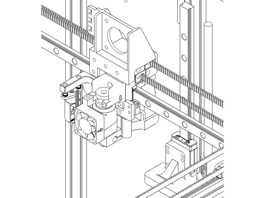
  • The E3D v6 should have been assembled already. It fits into the groovemount adapter as shown. It's best to turn it so the heat block is not too close to the fan shroud.

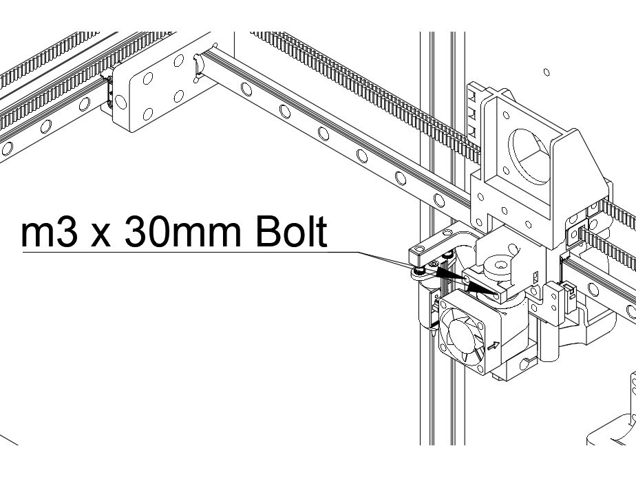
Step 2 — Hotend Retainer Clip

  • Use the hotend retainer (a small printed part) to fasten in the E3d v6 using (2) m3 x 30mm button head bolts.

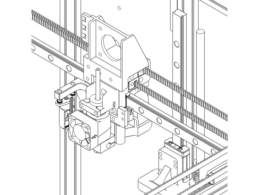
Step 3 — PTFE Tube

  • Insert a length of PTFE into the hotend, at least 91mm long. (You want around 45mm sticking out of the hotend when it's fully seated)

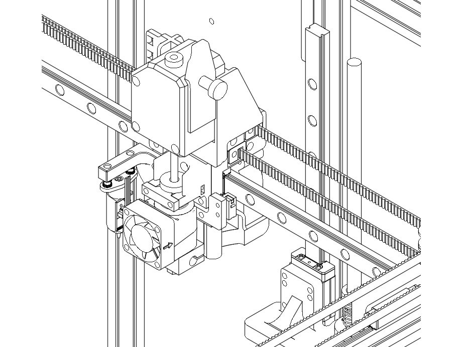
Step 4 — Bondtech BMG Extruder

  • Place the bowden coupler in the BMG mount
  • Slide the bowden tube onto the PTFE, and fit the BMG into the extruder mount
  • Trim down the ptfe slightly, until the BMG fits correctly in the mount - You want the ptfe tube as long as possible, so it's fully seated in both the hotend, and the BMG. The PTFE should end up with around 41mm sticking out of the hotend)

Step 5 — Pancake Stepper

  • Attach the BMG toothed gear onto the pancake stepper motor.
  • Fit the stepper motor through the BMG (it helps to take the front off of the BMG)

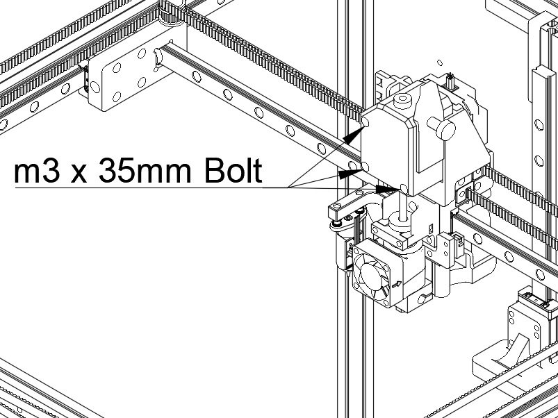
Step 6 — Bolt the BMG to Stepper

  • Fasten the BMG and stepper together on the extruder mount using (3) M3 x 35mm bolts. (These bolts come with the BMG)

Step 7 — X Endstop Assembly

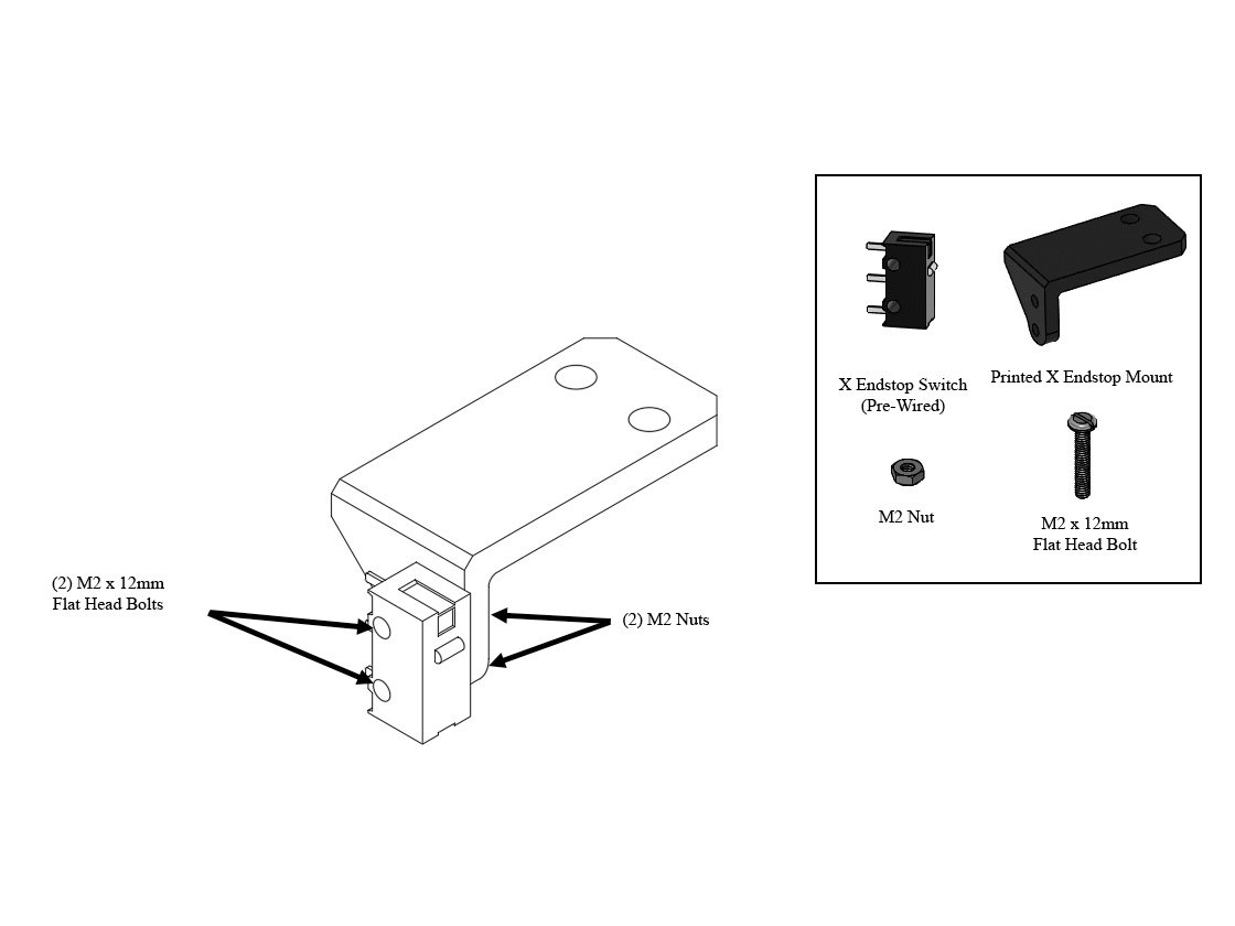
  • Attach the X Endstop (it comes pre-wired) to the printed X Endstop Mount using (2) M2 x 12mm Flat Head Bolts and (2) M2 Nuts
  • Note Don't worry about the wire for now, it's routed later.

Step 8 — X Endstop Installation

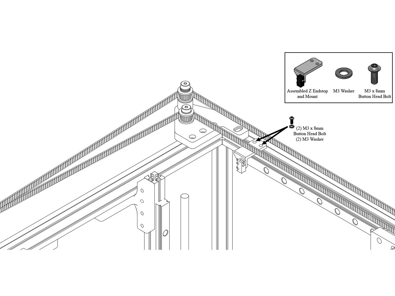
  • Mount the X endstop to the rear left corner of the frame, on the top Extrusion, using (2) M3 x 8mm Button Head Bolts and (2) M3 Washers.
  • Note Don't worry about exact placement for now, it will be adjusted later.

N) Aligning your RailCore

Step 1 — Align the Belts

  • The first step is to align your belts. Adjust the steppers so there's some tension - doesn't take much, just enough that the belts are straight.
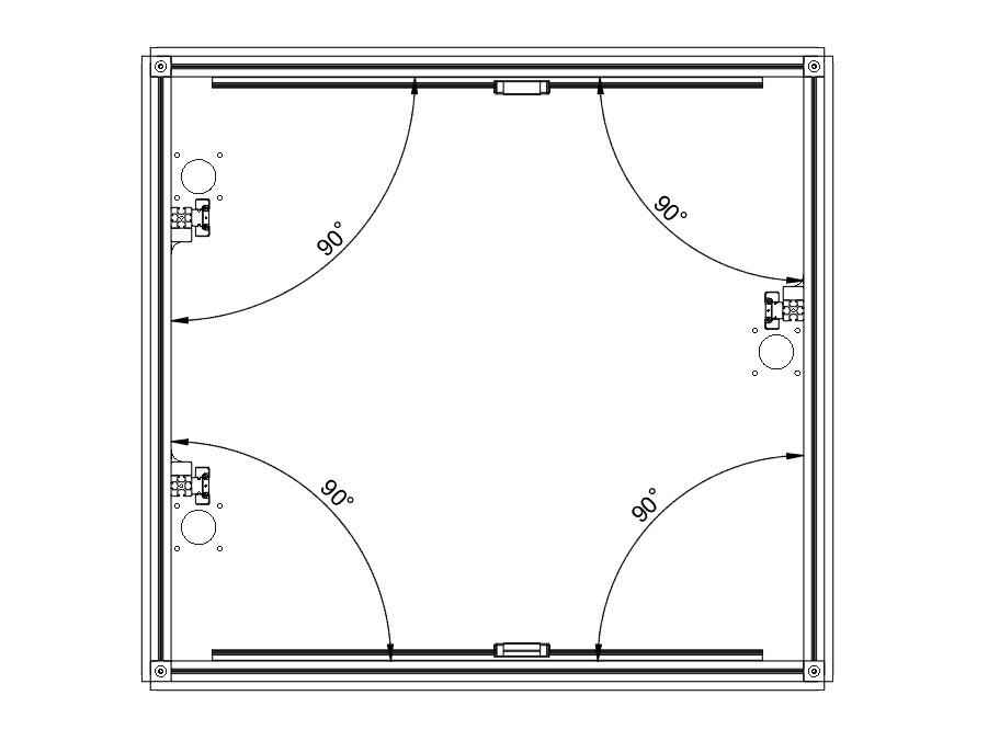
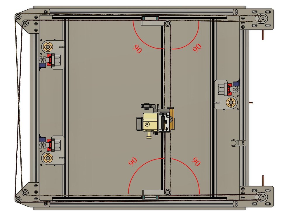
  • Loosen the bolts holding each stepper and idler mount, and move them on the frame until the belts form 90 degree angles to each other.
  • Caution If you have a Halo, this alignment is done automatically.

Step 2 — Tension the Belts

  • Earlier in the process you should have made sure your belts are equal lengths, if you did, that will make getting proper tension easier.
  • Caution Each X Carriage has two bolts retaining the Y rail in place. Loosen those bolts in both carriages just a little before proceeding. (They should still keep the rail in position, but should not be tight)
  • Pull on the Front stepper in the mounts to lightly tension the front belt. You don't need too much tension.
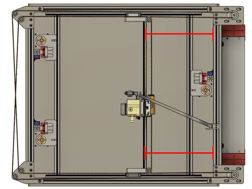
  • Pull the rear stepper back in the mount until the measurements marked in red on the image are equal. (Measure from the right side of the Y rail marked in red, to the left side of the top right extrusion where marked in red).
  • Caution 1-2-3 blocks can be used in place of measuring.
  • Once the Y rail is squared you should re-tighten the bolts in the X carriages to retain the Y rail.
  • Ideal belt tension is between 40 - 50hz as measured on the short spans on the left of the printer between the idler mounts.

Step 3 — Centering the Linear Rails

  • Loosen all the bolts holding your linear rail to one Z extrusion. Adjust the Rail so it's 20mm above the bottom panel.
  • Tighten only the top bolt holding the rail to the extrusion.
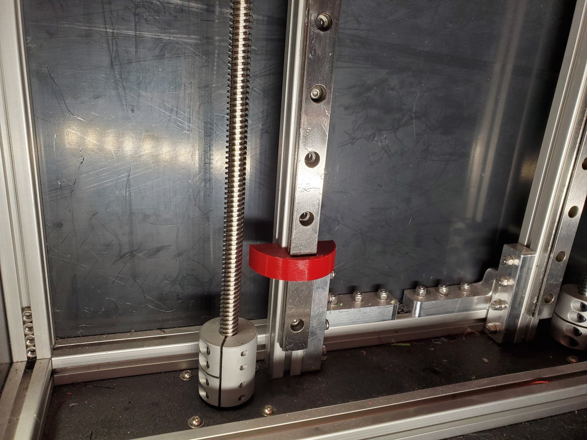
  • Place the Rail Alignment Tool over the linear rail near the bottom bolt. This will center the linear rail on the extrusion. Tighten the bottom bolt.
  • Loosen the top bolt. Now work your way up from the bottom, putting the rail alignment tool near each bolt, then tightening it.
  • Repeat this process for each of your Z rails.
  • Repeat this process for your X rails, working end to end. Center the X rails in the extrusion.

Step 4 — Aligning the Z Towers

  • There is a video on aligning the Z towers here: https://www.youtube.com/watch?v=CNWzMLc5...
  • Loosen the bolts in the Z brackets for one tower, so it can move freely.
  • Lower the Z yoke by spinning the lead screw, until the yoke is just above the leadscrew coupler.
  • Tighten down the lower Z bracket, be sure the Z extrusion is pushed flush against the side extrusions as you tighten the brackets.
  • Move the yoke into the center of the Z tower.
  • Use a calipers or a ruler to measure from your front panel to the Z extrusion at the bottom.
  • Repeat the same measurement near the top of the Z tower, and adjust until it's equal.
  • Tighten the top of the Z tower. Repeat for all 3 towers.

Step 5 — Adjust X Endstop

  • Loosen your X endstop mount. Move it to the left side of the rear extrusion.
  • Manually move the Y rail until the hotend is approx 5mm from one of the left leadscrews.
  • Move the X endstop to be against the rear X carriage, be sure the switch triggers.
  • Tighten down the X endstop.

O) Bed

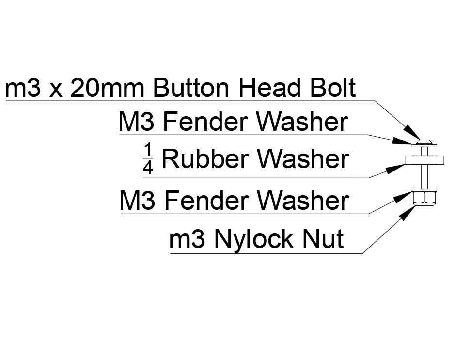
Step 1 — Assemble the Bolt Stacks for Attaching the bed

  • It works best to build the bolt stacks for attaching the bed, then put them in place on the yokes.
  • (Filastruder kits use a Socket Cap Head Screw in place of a button head bolt)
  • On a 20mm Button Head Bolt place:
    • (1) M3 Fender Washer
    • 1/4 rubber washer
    • (1) M3 Fender Washer
    • (1) m3 Nylock Nut

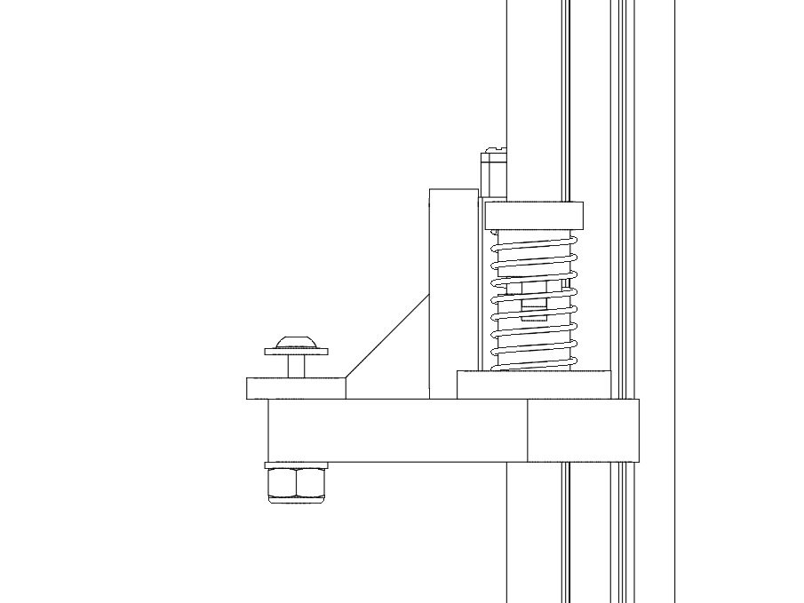
Step 2 — Put Bolt Stacks on the Yokes

  • Place the bolt stack on the yoke, so the Nylock nut and m3 fender washer are below the Yoke, and the 1/4 rubber washer is on top of the yoke.
  • Repeat for all 3 yokes.
  • Note The right yoke gets a ground wire from the bed wiring harness above the top washer. (not yet pictured). This requires a 25mm bolt to do as shown, currently the kits ship with only 20mm bolts, leaving out the lower washer is temporary fix.

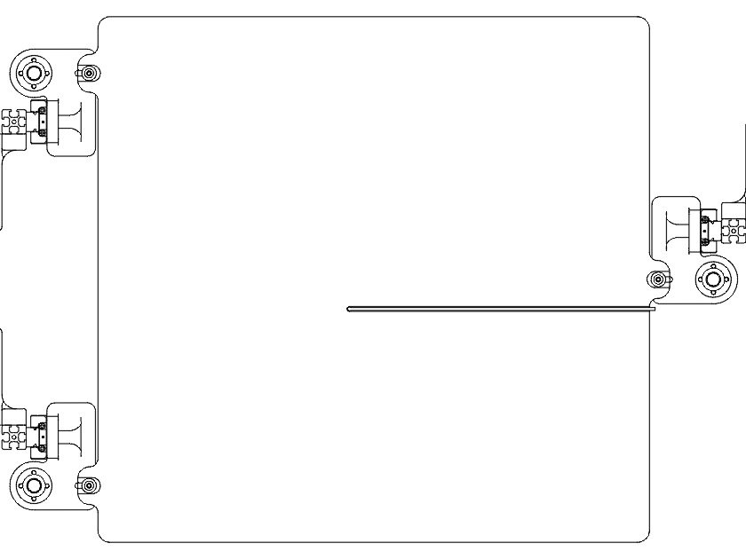
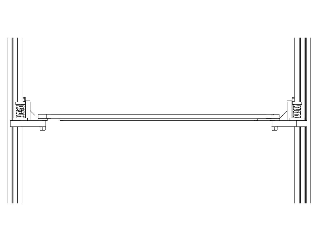
Step 3 — Install Bed

  • Install the bed by fitting it onto the yokes, with the best resting on the 1/4 rubber washers, and the m3 fender washer in the grooves on the bed tabs.
  • Snug up the m3 nylock nuts to hold the bed in place.

P) Electronics

Step 1

  • Caution Newer Filastruder kits use Socket Cap Head Screws, use them in place of all button head screws in this section unless noted.

Step 2 — Safety

  • Caution THE RAILCORE IS A “DIY” PROJECT - BUILD SAFE, BUILD SMART, AND BE RESPONSIBLE.
  • Caution BUILD AT YOUR OWN RISK.
  • Caution WHEN IN DOUBT, DOUBLE CHECK THINGS.
  • Caution 3D PRINTERS CAN GET VERY HOT. USE COMMON SENSE AND QUALITY COMPONENTS.
  • Caution If you need help, find us at the RailCore Facebook page or RailCore Discord channel. Both are linked from RailCore.org

Step 3 — Power Supply

  • Caution Check the voltage setting on the side of your Power Supply before installing it.
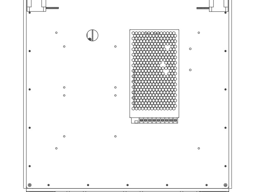
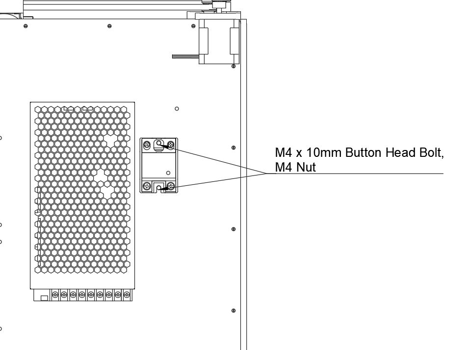
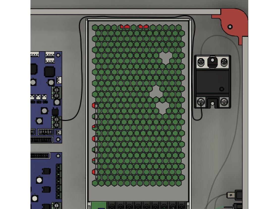
  • Attach the PSU using (4) M4 x 10mm Button Head Bolts. The bolts go through holes in the right panel, and into the back of the PSU.
  • Be sure to install the PSU so the wiring terminals are to the bottom of the printer.

Step 4 — SSR

  • Install the SSR as shown.
  • Each hole is held in place using (1) M4 x 15mm Socket Cap Head Screws and an M4 nut & Washer

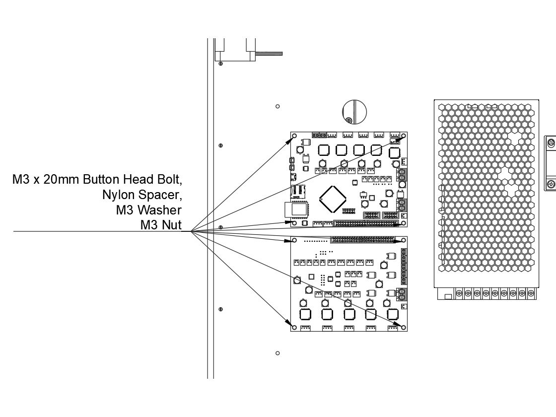
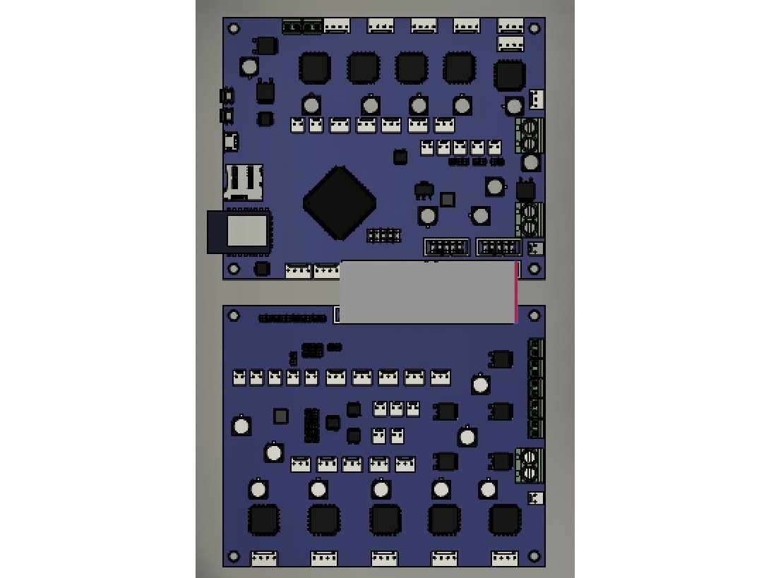
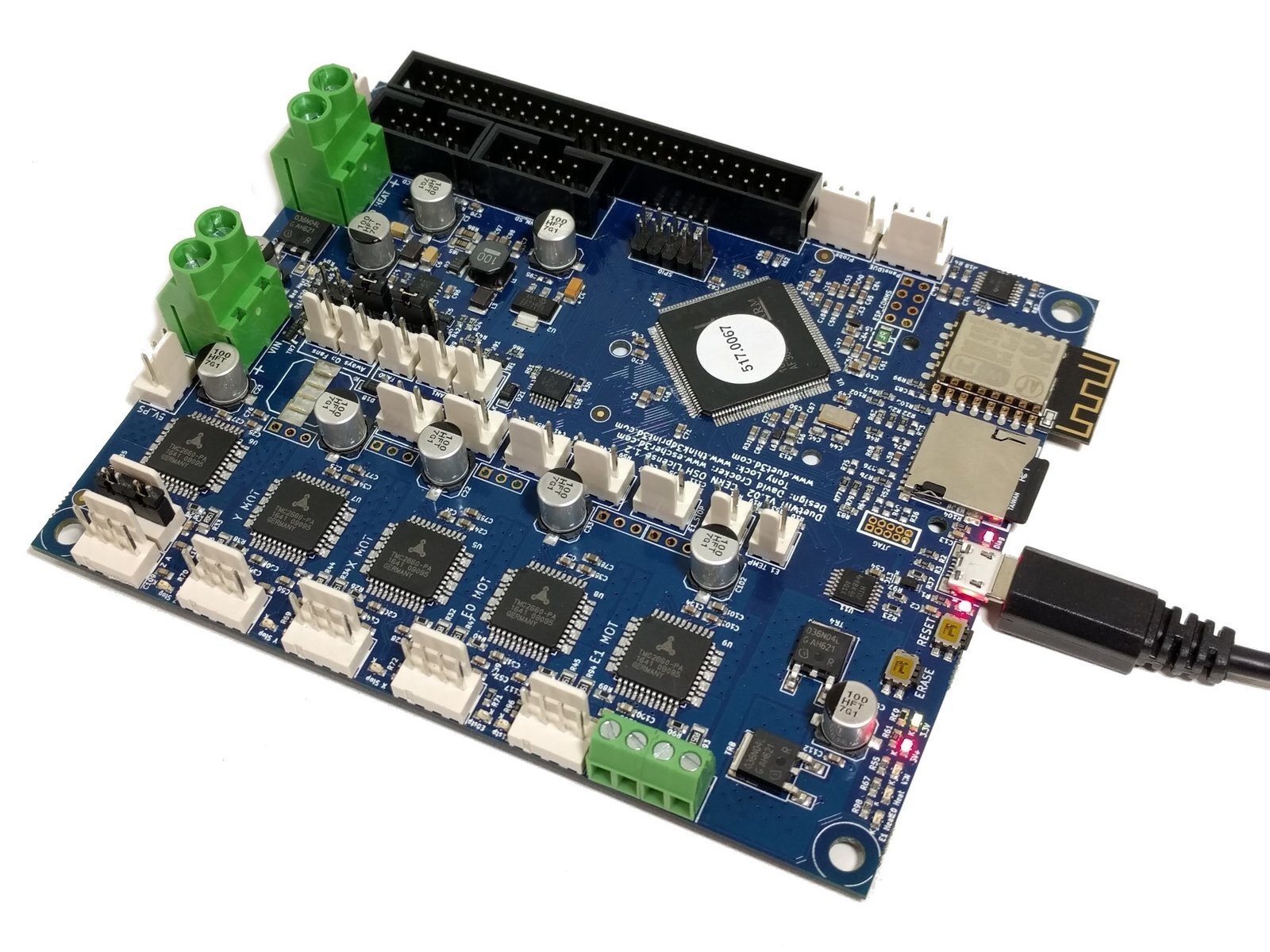
Step 5 — Duet and Duex5

  • Attach the Duet and Duex5.
  • Be sure the Duet is on top, Duex5 is on bottom.
  • Pay careful attention to the orientation.
  • Mount them by putting one M3 x 16mm bolt through the board. Put the black nylon 5mm tall spacer behind the board.
  • Note The image says 20mm, it needs to be corrected.
  • Pass the bolts through the panel, attach with an M3 Washer and M3 nut.

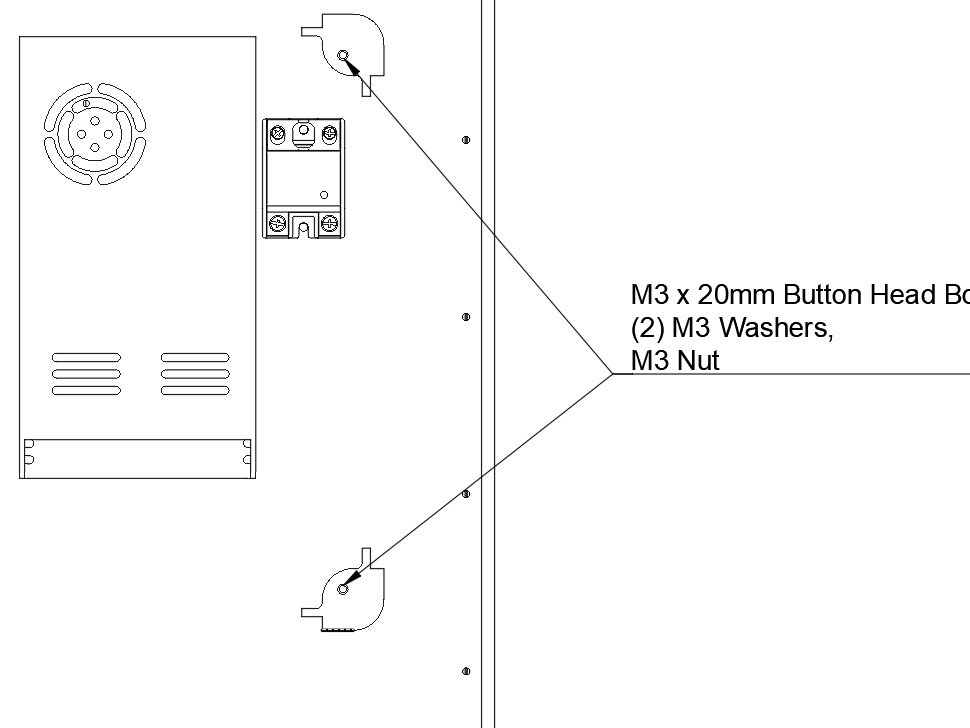
Step 6 — Rear Ebox Corners

  • Attach the two rear Ebox Corners.
  • Use an M3 x 16mm Socket Cap Head Screws and washer.
  • Note Image says 20mm bolt, will be corrected
  • Pass them through the short side of the Ebox corner, and through the right panel.
  • Fasten with an M3 washer and M3 nut.

Step 7 — Power Switch

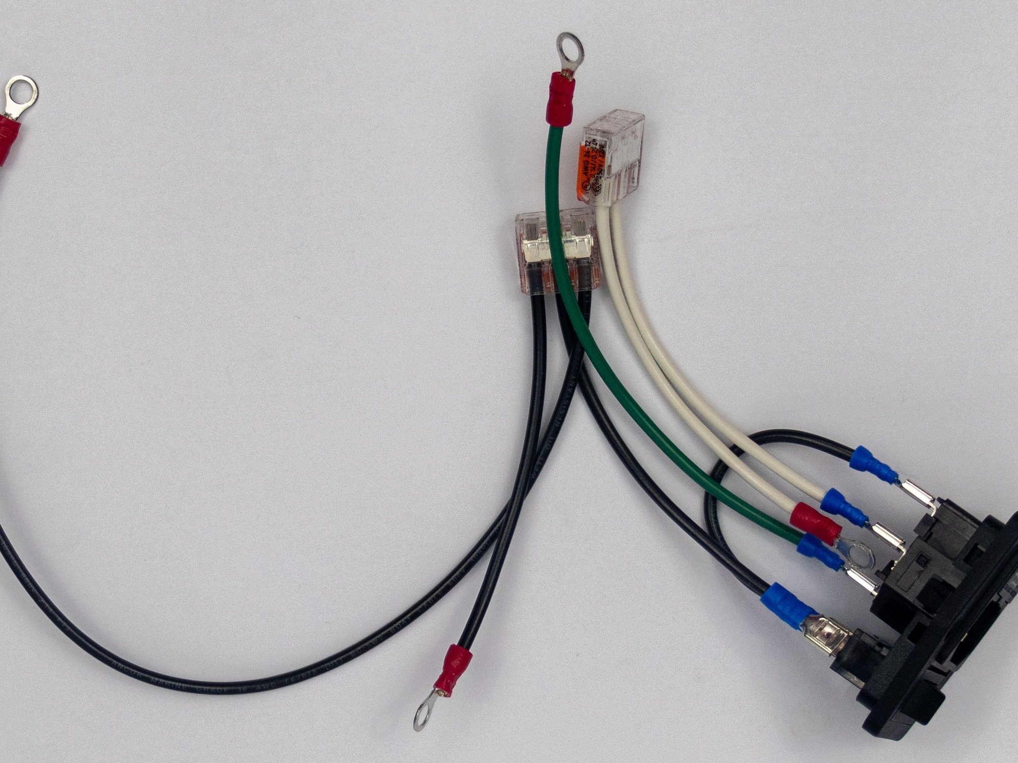
  • The power switch in your kit should come pre-wired. This guide will walk you through it if it's not, and also serve as a way to double check it.

Step 8 — Power Switch

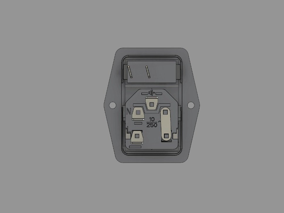
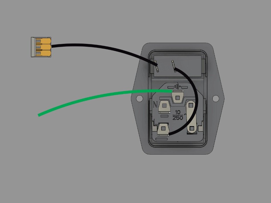
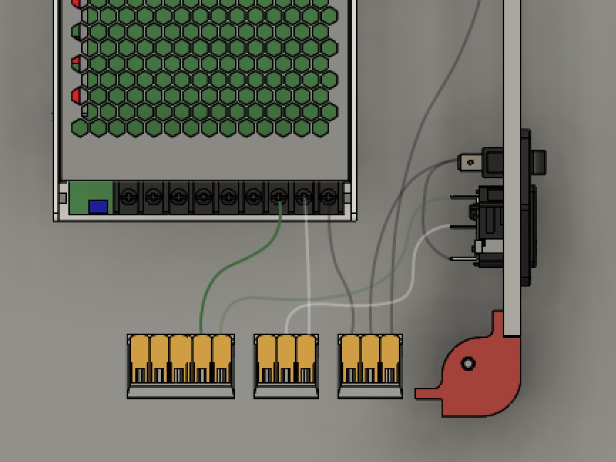
  • If your switch isn't already wired, lay it face down as shown.
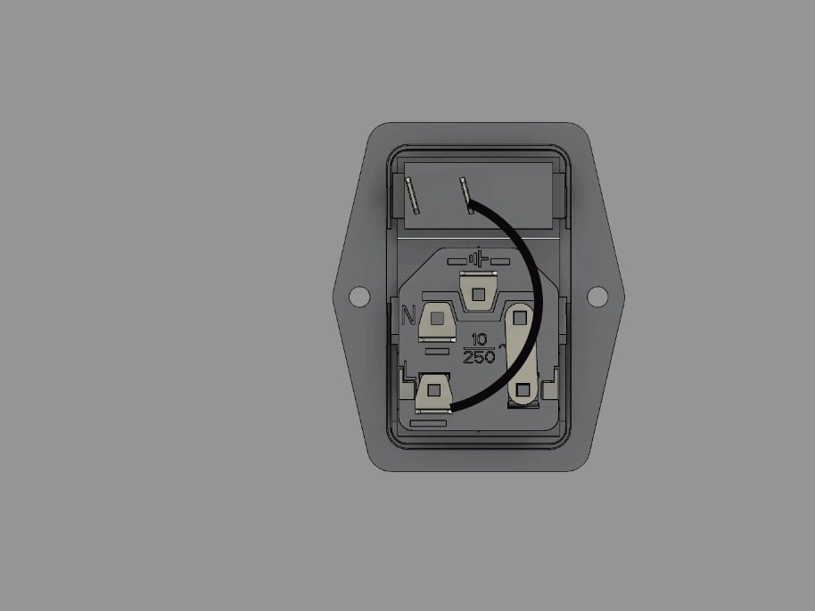
  • Install the 75mm black wire between the switch and the fuse. It's a short black wire, with a spade terminal on each end.
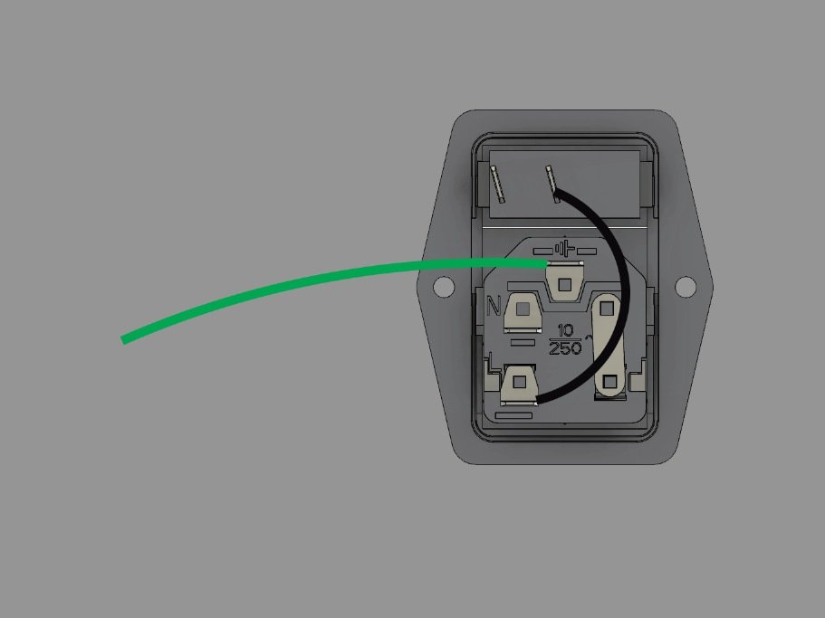
  • Install the 150mm green ground wire to the ground terminal on the plug. It has a spade terminal on one end, and a ring terminal on the other.

Step 9 — Power Switch

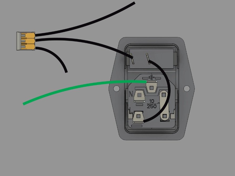
  • Install the 100mm black wire onto the other terminal on the switch. One end is a spade terminal, the other end is bare wire, and goes into a 3 connector WAGO.
  • Add a 80mm black wire with a ring terminal into one slot in the WAGO, and a 300mm black wire with a ring terminal into the other slot in the wago.

Step 10 — Power Switch

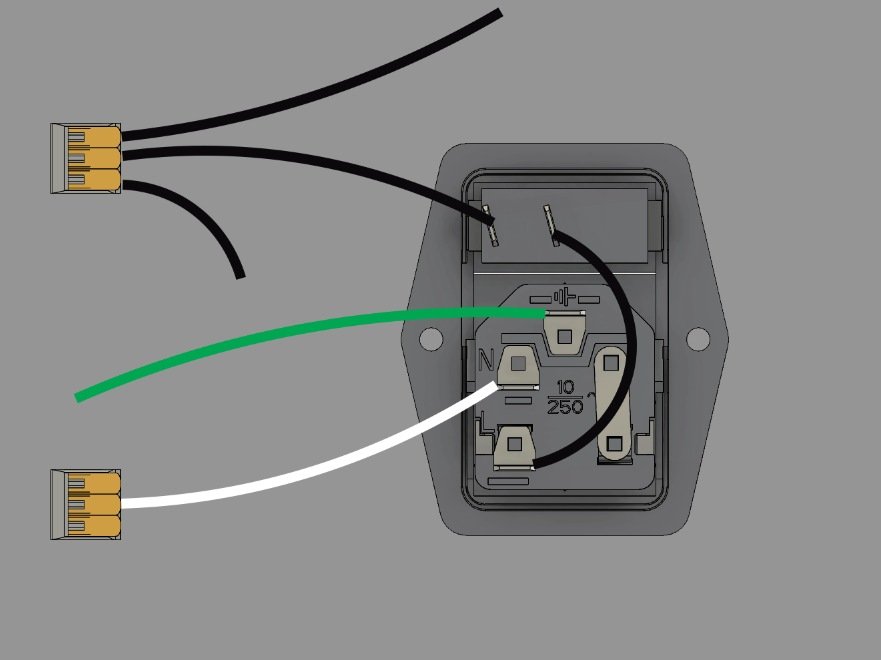
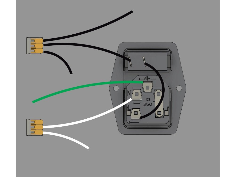
  • Install a 100mm white wire into the remaining spot on the plug with a spade connector. The other end of the wire is bare, and goes into a 3 slot WAGO connector.
  • Add the bare end of a 100mm white wire into the WAGO. The other end has a ring connector.

Step 11 — Power Switch / Plug

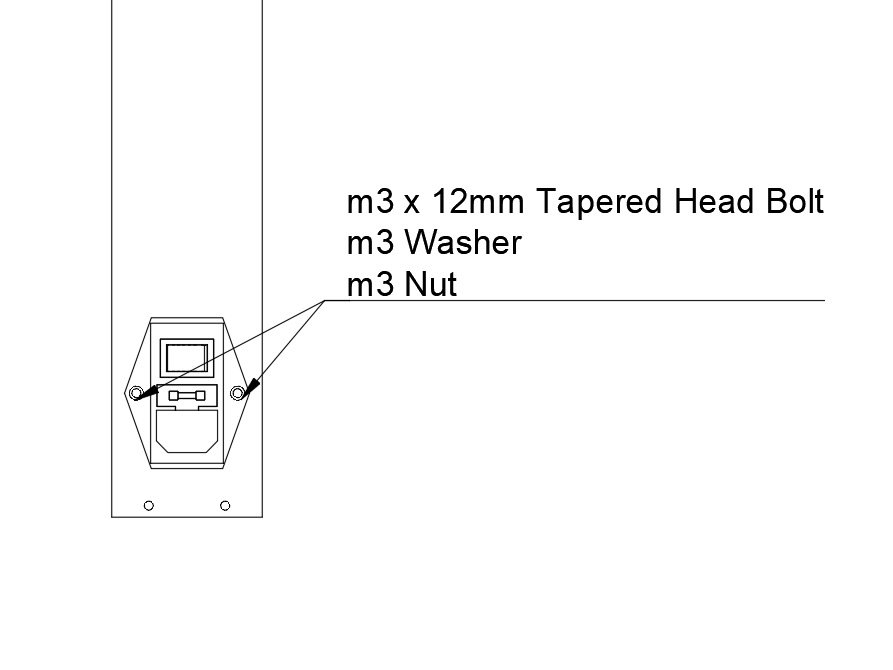
  • Install the assembled and wired Power Switch / Plug module into the rear Ebox Panel.
  • Pass the wiring already attached to the plug through the panel.
  • Insert (2) M3 x 12mm Tapered Head Bolts through the switch and panel.
  • Fasten using an M3 washer and M3 nut.

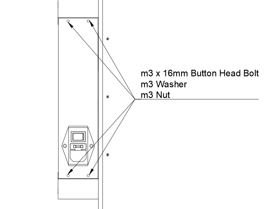
Step 12 — Rear Ebox Panel

  • Install the Rear Ebox panel onto the Ebox corners you've installed.
  • Pass an M3 x 16mm Button Head Bolt through each of the panel holes.
  • Fasten each bolt using an M3 washer and M3 nut.

Q) Wiring the Electronics

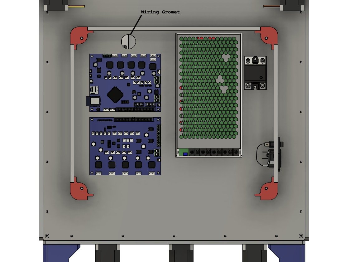
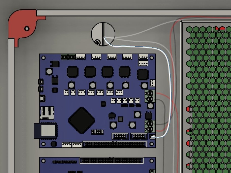
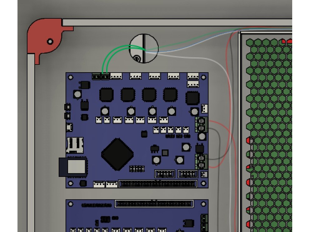
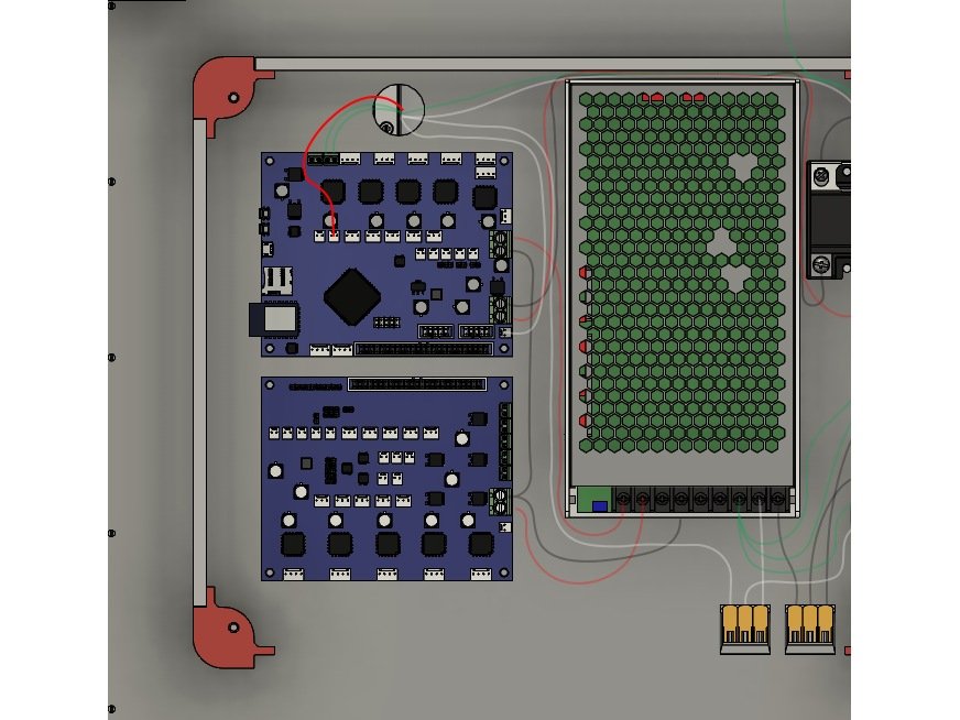
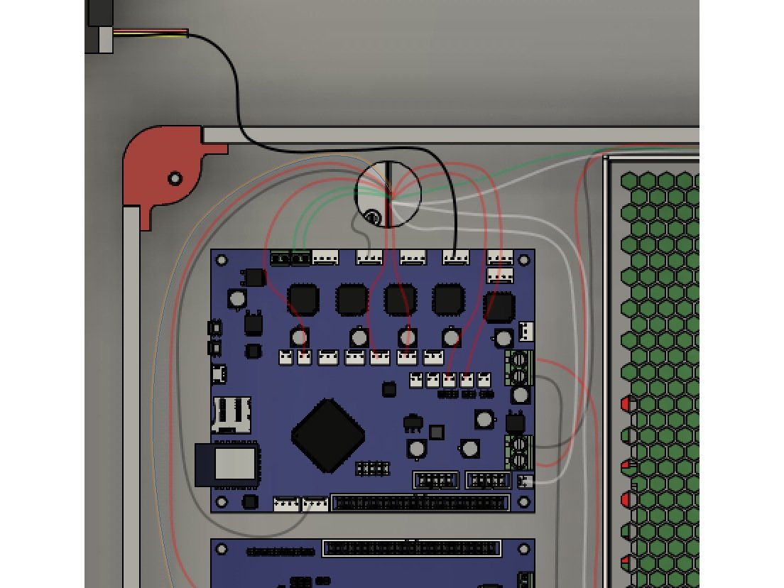
Step 1 — Wiring Grommet

  • Note The top and left panels are pictured for reference - they're not actually installed yet because it makes the wiring much easier to route.
  • Install the grommet in the panel, to keep the wires from rubbing. If you've already pulled any of the wires through, you'll need to remove them to add the grommet.
  • Both the wire bundle from the bed, and from the hotend, will run through this hole.
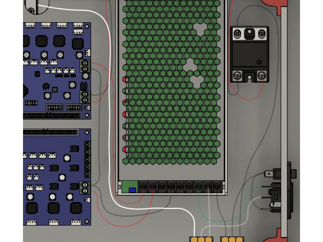
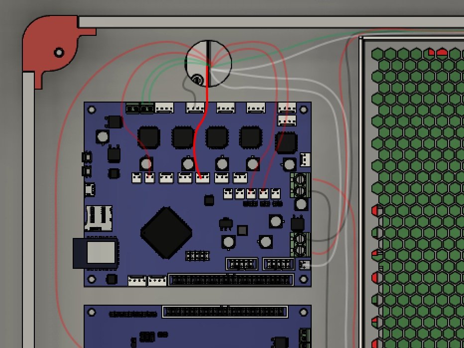
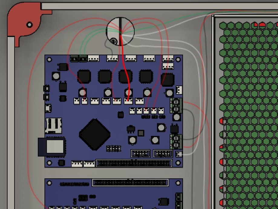
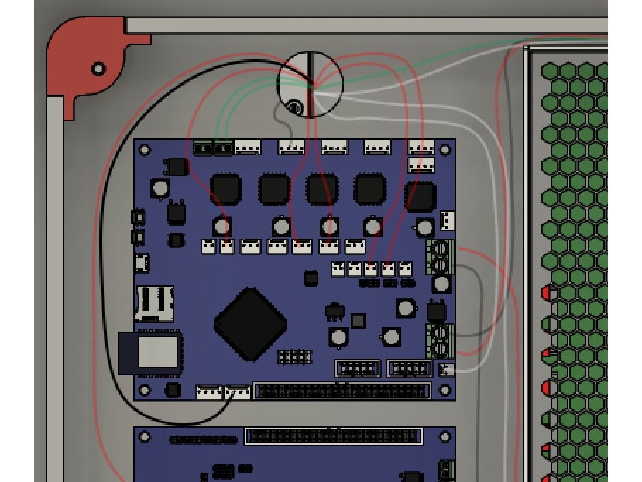
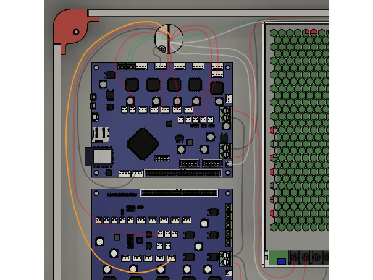
  • Install the Ribbon Cable between the Duet & Duex5. Note the red strip should go to the right.
  • You can tuck the excess length of the ribbon cable under the Duex5 to help keep things tidier.

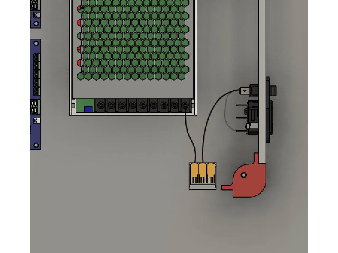
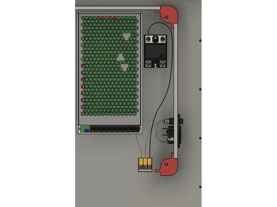
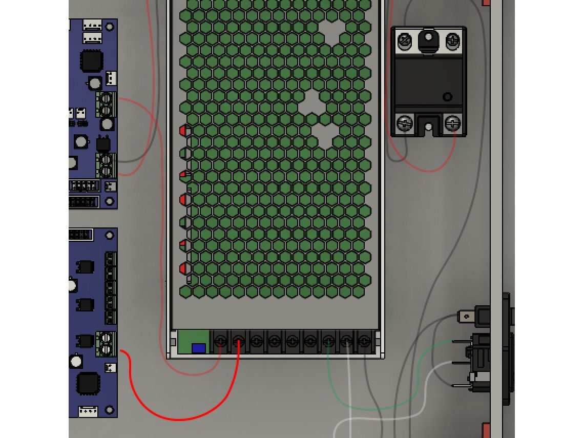
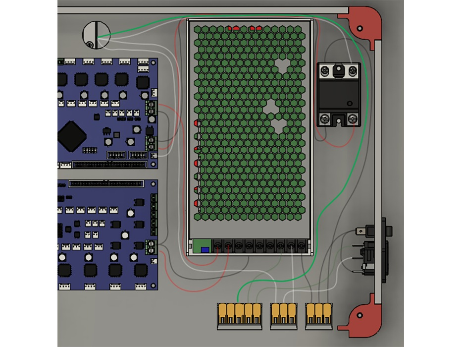
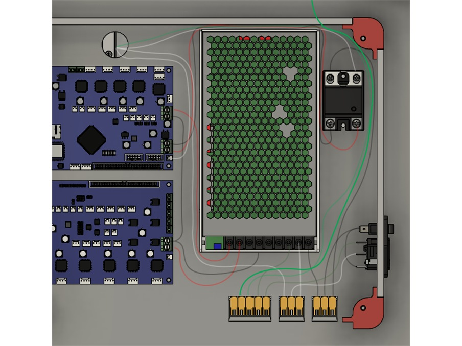
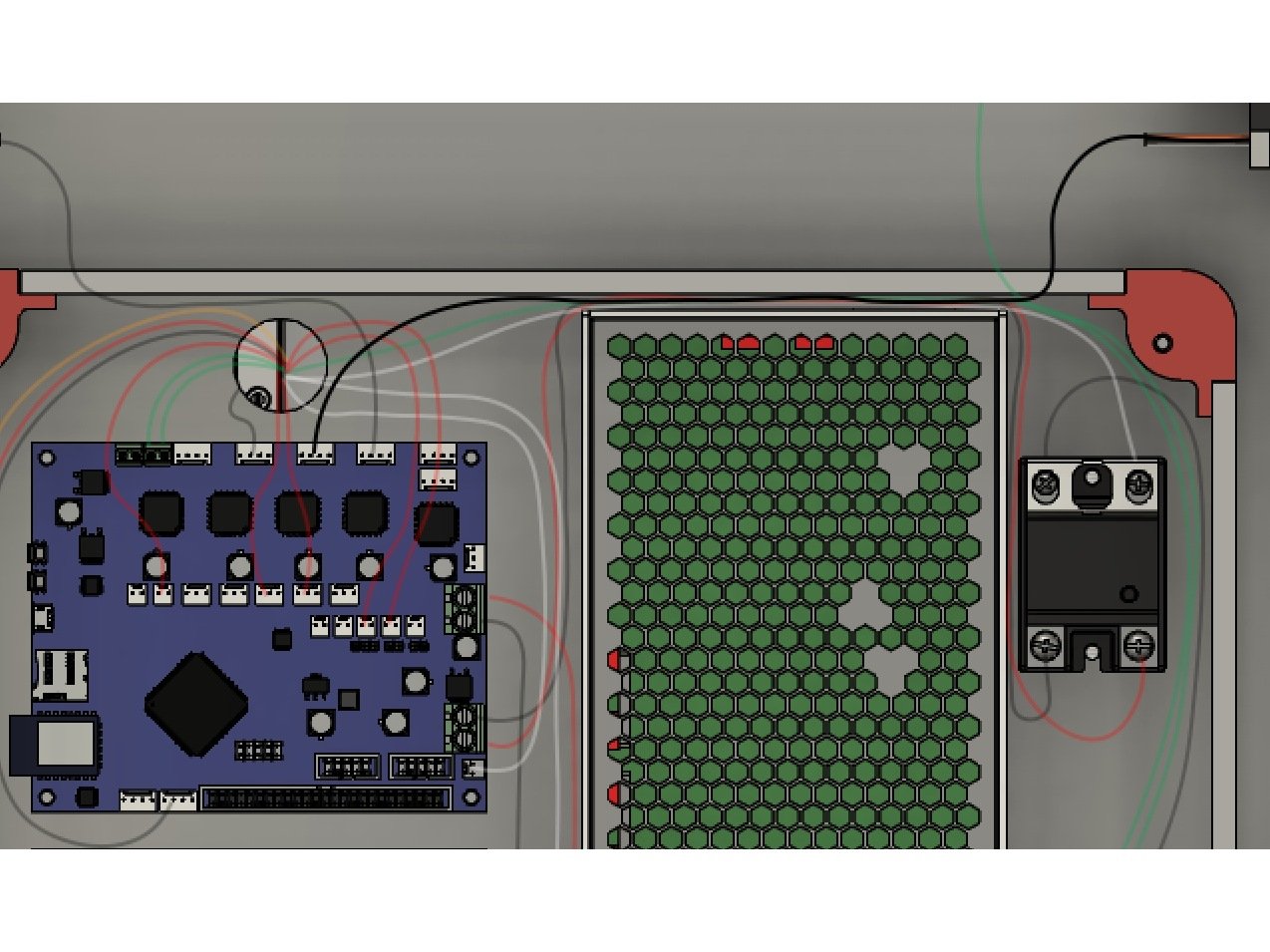
Step 2 — Switch to PSU

  • Connect the short black wire from the WAGO connector to the port marked L on the PSU using the ring terminal.

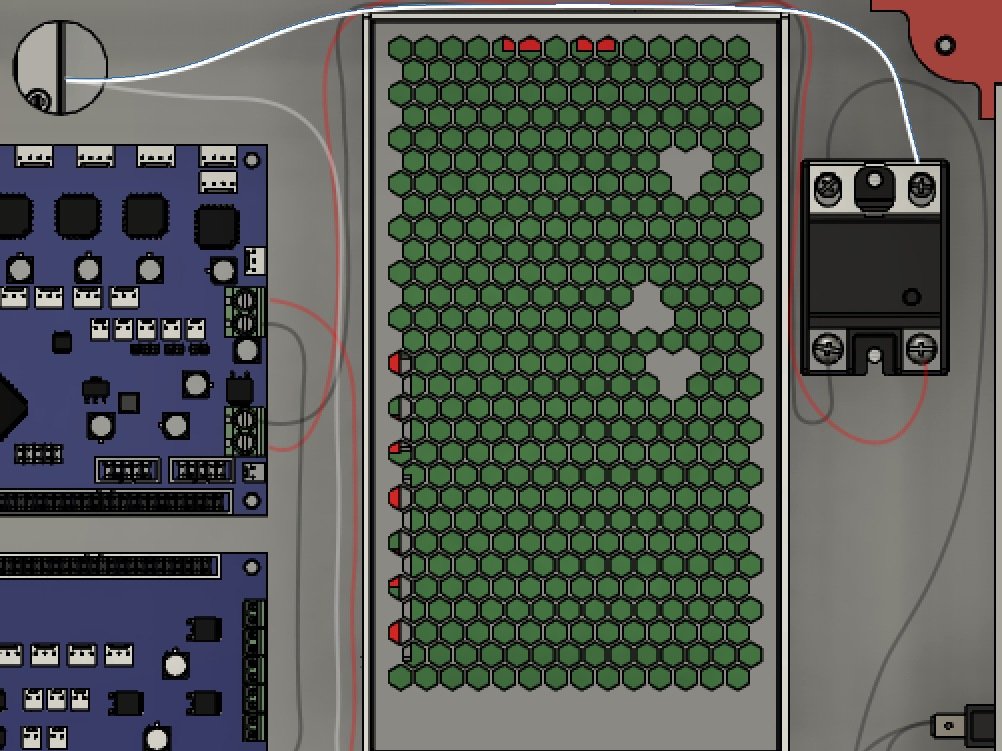
Step 3 — Switch to SSR

  • Connect the long black wire from the WAGO connector to the ring terminal marked 1 on the SSR.
  • The SSR has a protective plastic cover over the AC terminals, #1 & #2. This cover needs to be opened (flipped back) to fully remove the terminal screw for the ring terminal. The screw is mildly captive, so continue unscrewing to release it. Re-install the snap cover after installing both #1 & #2.
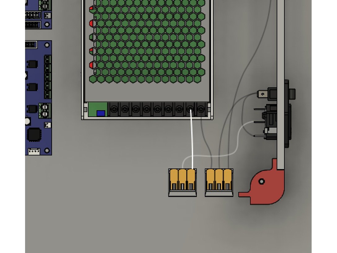
Step 4 — Plug to PSU

  • Use a WAGO to connect both the White (Neutral) lead from the AC Plug and a short white wire with a Ring terminal.
  • Attach that ring terminal to the port marked N on the PSU.

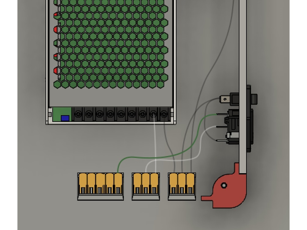
Step 5 — Ground Wire

  • Connect the green ground wire from the plug to the 5 port WAGO connector.

Step 6 — PSU Ground

  • Connect a green wire from the 5 port WAGO to the ground terminal on the PSU.
  • The Ground terminal is designated with the Earth Ground ⏚ symbol

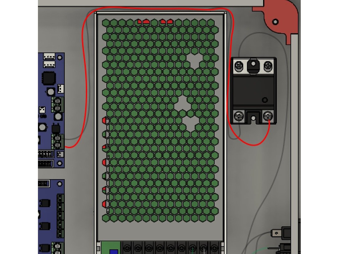
Step 7 — SSR to Duet Bed Negative

  • Use the long black wire for the SSR to Duet. The SSR end has a ring terminal, and goes in SSR port 4.
  • The other crimped end goes in the Duet Bed "-" terminal.

Step 8 — SSR to Duet Bed Positive

  • Connect the long red wire to the SSR port 3 using the ring terminal.
  • The other crimped connector goes into the Duet Bed "+" terminal.

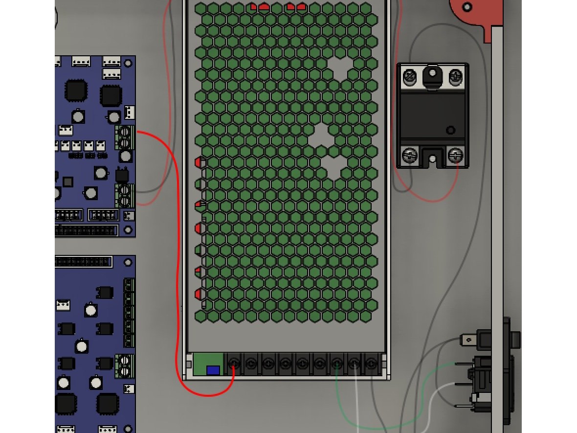
Step 9 — PSU to Duet Positive

  • Connect the red wire ring terminal to the PSU "+" connector.
  • Connect the end marked Duet to the "+" power input on the Duet.

Step 10 — PSU to Duex5 Positive

  • Connect the short red wire with the Duex5 label's ring terminal to the PSU "+" connection.
  • The crimped end goes in the Duex5 "+" terminal.
  • Caution Be sure to note which terminal is the Duex5 "+" terminal. It is the opposite of the Duet2.

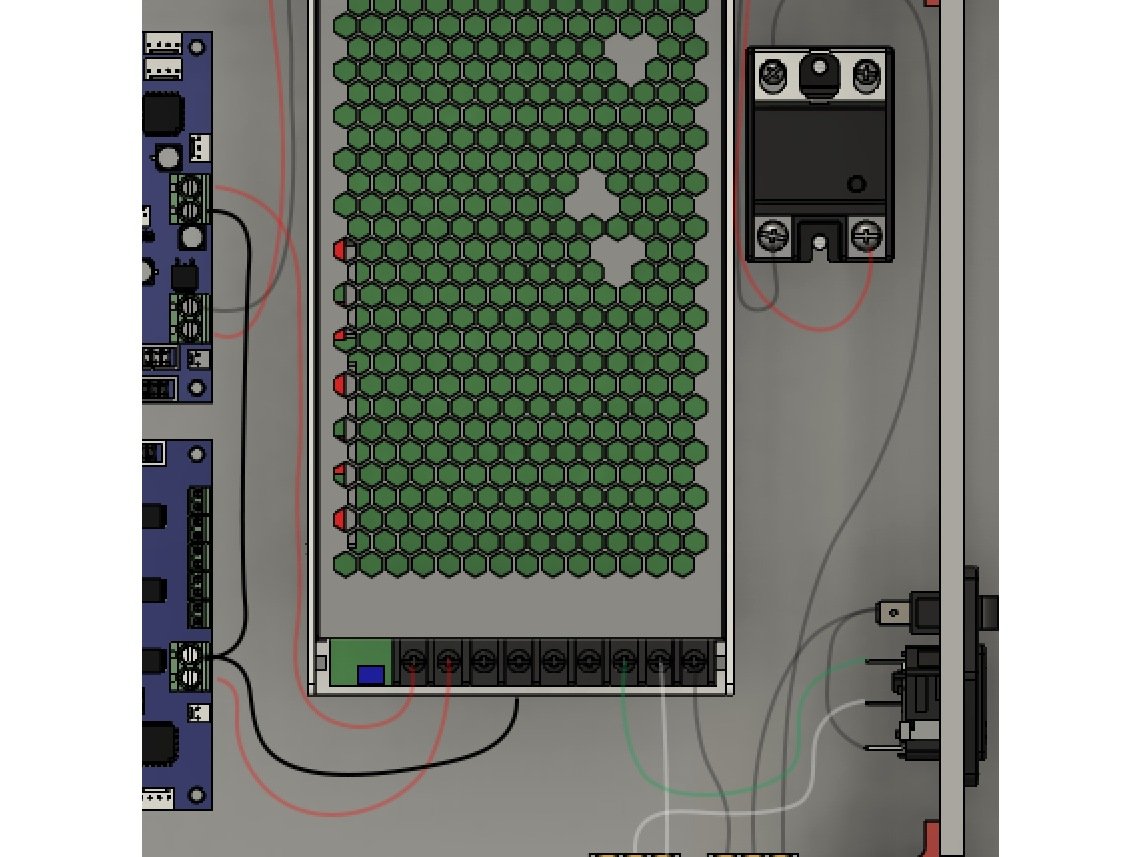
Step 11 — PSU to Duex to Duet2 Negative

  • Connect the ring terminal on the Y cable to the PSU "-" connection.
  • The center crimped connection goes in the Duex5 "-" power connector.
  • The other crimped connection goes in the Duet2 "-" power connector.

Step 12 — Bed to Neutral

  • The bed has two white braided wires coming from it. One of them is longer, and has a bare end.
  • Straighten out the wired on the bare end. Lift up the arm for the open spot on the WAGO connector.
  • Insert the wire into the WAGO, and close the lever arm.

Step 13 — Bed to SSR

  • The shorter end of the white braided bed wires has a ring terminal on it.
  • Connect the ring terminal to the SSR port 2.

Step 14 — Bed Thermistor

  • The bed wiring has two thin white wires with a molex connector for the bed thermistor.
  • Connect these wires to the bed thermistor port on the Duet2.

Step 15 — Bed Ground

  • The bed harness has a green ground wire that was attached to the bed earlier in the build.
  • Run the ground wire over the PSU and SSR, down to the 5 port WAGO the green wires from the PSU and Power Inlet were run to.

Step 16 — Frame Ground

  • There is a long green ground cable used for grounding the frame. It has ring terminals on one end.
  • One end goes in the same 5 port WAGO as used for the bed ground, Power Inlet Ground, and PSU ground (green wires)
  • Run the cable up past the SSR, and attach it to the top frame on the extrusion near the rear stepper.
  • Use the toothed lockwasher and an M3 x 8mm button head bolt. Place the toothed washer under the ring terminal.

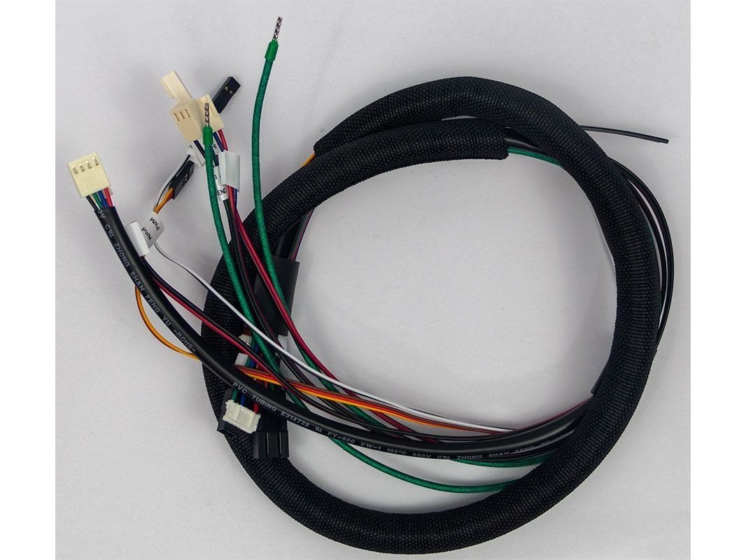
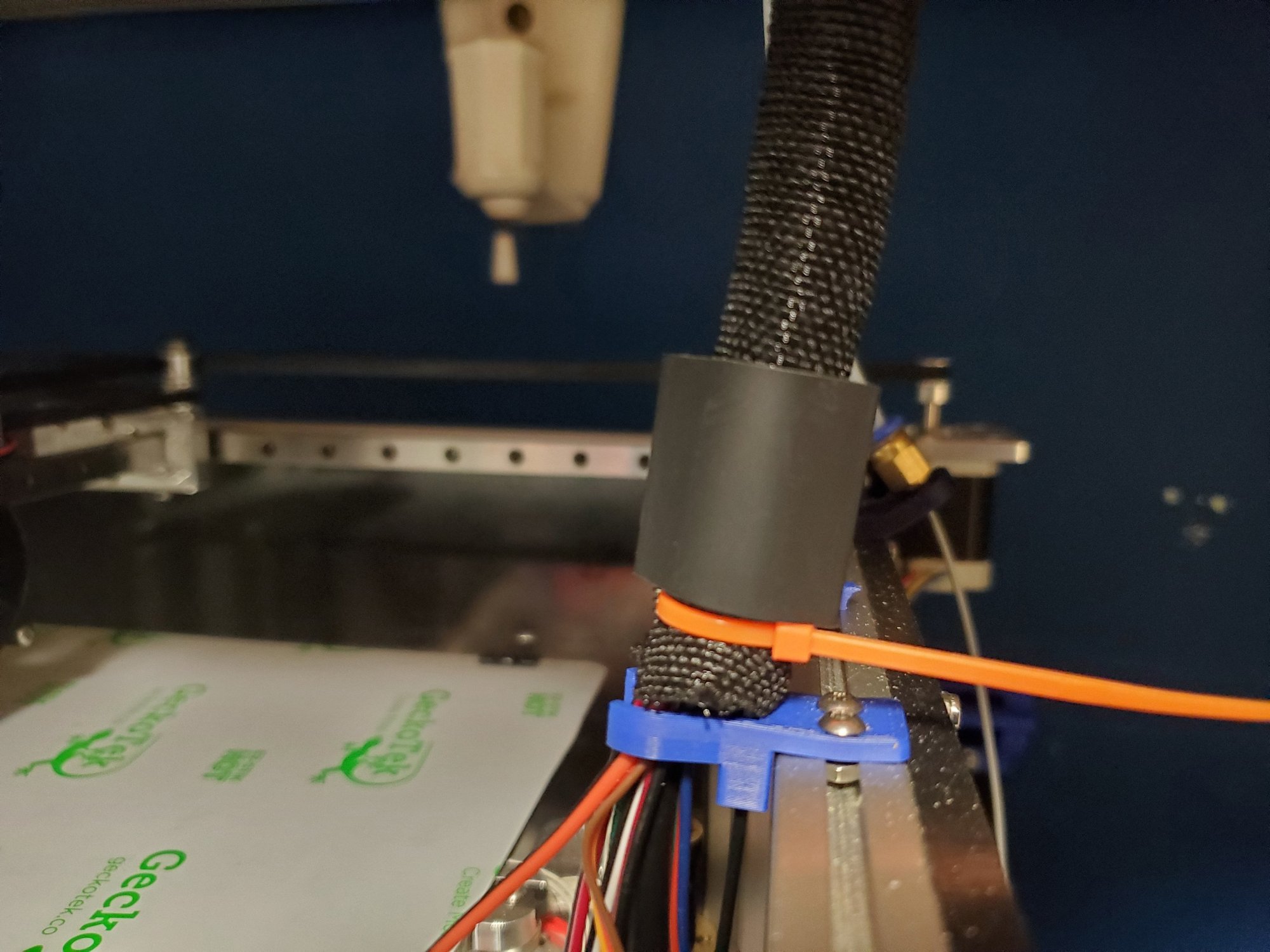
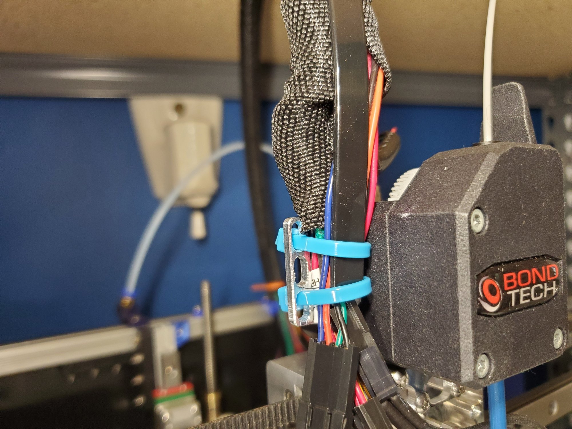
Step 17 — Extruder Wiring Bundle

  • All of your Y carriage items should already be mounted. Now you'll add the wiring harness for the hotend.
  • There is a 36" zip tie inside the wiring bundle. One end of it slots into the wiring clip on the right side of the printer.
  • Run the ends of all the wires through the grommet you installed.
  • The other end gets zip-tied to the wiring mount on the extruder mount.

Step 18 — Extruder Wiring

  • Caution Photos of these steps will be added ASAP
  • You'll need to remove the wiring that came pre-installed on the BLTouch if you haven't already. The wiring harness includes a new BLTouch connector.
  • Connect the hotend, hotend fan, thermistor, BLTouch, and the Fan/Y Endstop.
  • You may need to pull the wires further through the wiring harness in one direction or the other to make them reach, or to reduce slack. You don't want them super taught, but you don't want a lot of slack on the extruder end once they're connected.

Step 19 — X Endstop wiring

  • Caution Images for this step will be added ASAP
  • The X Endstop was installed earlier.
  • The X Endstop wire can be pushed into the bottom of the top rear extrusion to the right rear corner, then into the bottom channel of the top right extrusion, until it gets to the hole in the panel for the wiring.

Step 20 — Hotend

  • There are two cloth wrapped green wires for the hotend. The ends have crimped bootlace connectors.
  • Insert the connectors into the E0 heater port on the duet, and carefully tighten it down with a screwdriver.

Step 21 — Hotend Thermistor

  • The Hotend Thermistor is a red and black pair of wires. Plug it in to the E0 Temp port on the Duet2.

Step 22 — Extruder Stepper

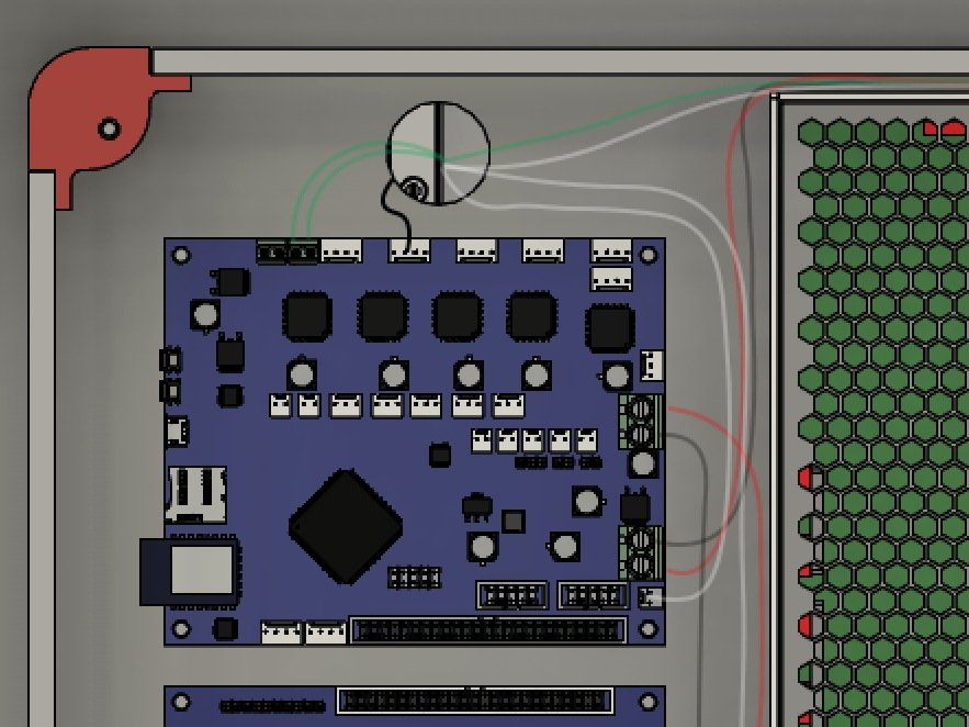
  • Connect the extruder stepper wire to the 4-pin E0 Stepper port on the Duet2.

Step 23 — Hotend Fan

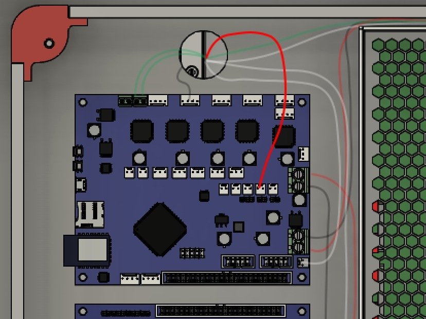
  • Connect the Hotend Fan to one of the always on Fan ports on the Duet2.
  • Caution It's good to double check that the red wire is to the right side pin, nearest the Duet2 Power connectors.

Step 24 — Layer Fan

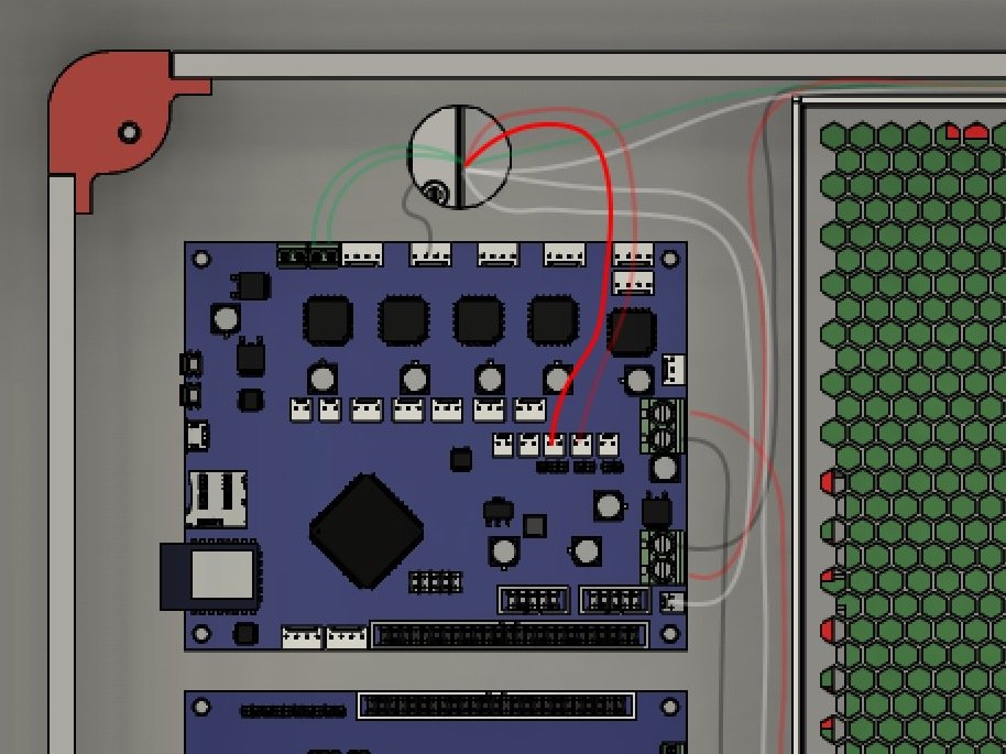
  • Connect the Layer Fan wires to the Fan0 connector on the Duet2.
  • Caution It's best to double check the red wire is on the right side pin, nearest the Duet2 power connectors.

Step 25 — Keenovo Thermistor

  • The Keenovo comes with its own thermistor. It's not used to control the bed temp, we use the one in the channel on the bed. However it can be used as an extra bed temp monitor.
  • The keenovo thermistor wires are two red wires with a molex connector. Connect it to the E4 Thermistor port on the Duex5.

Step 26 — X Endstop Wiring

  • Connect the X Endstop wire to the X_Stop connector on the Duet2.

Step 27 — Y Endstop

  • Connect the Y endstop connector to the Y_Stop port on the Duet2.

Step 28 — Z Probe

  • The Z Probe connector is a black and white wire pair. It goes to the left two pins in the Z_Probe connector on the Duet2.
  • It is important that the white wire is on the left in the first pin, nearest to the PanelDue connector, and the black wire is on the right to the second pin.

Step 29 — BLTouch

  • The 3 wire connector for the BLTouch goes to the PWM1 port on the Duex5.
  • Caution The wire color, from left to right, is Orange, Red, Brown.

Step 30 — Y Stepper

  • The Front Stepper Cable (Y Stepper) cable plugs into the connector on the stepper.
  • The other end of the connector goes to the Y Motor connector on the Duet2.

Step 31 — X Stepper

  • Connect the Rear X Stepper to the X_Motor port on the Duet2.
  • Caution Double check the X/Y Stepper connections are in the correct ports - if they're incorrect you will have motion issues.

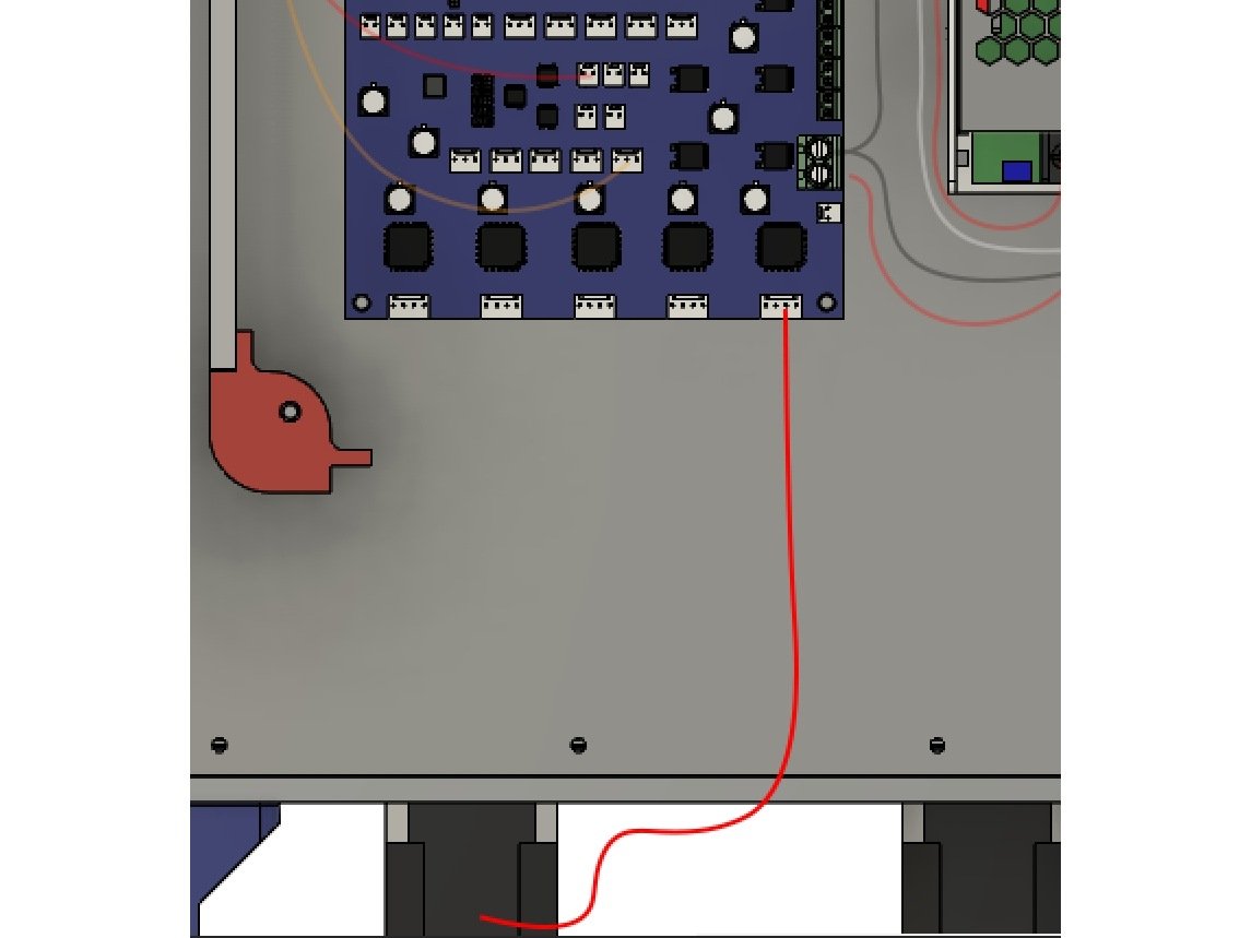
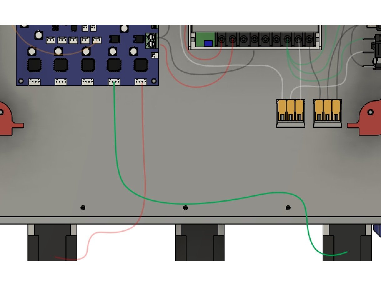
Step 32 — Front Left Z Stepper

  • For the Z steppers it can help to lay the printer on its back.
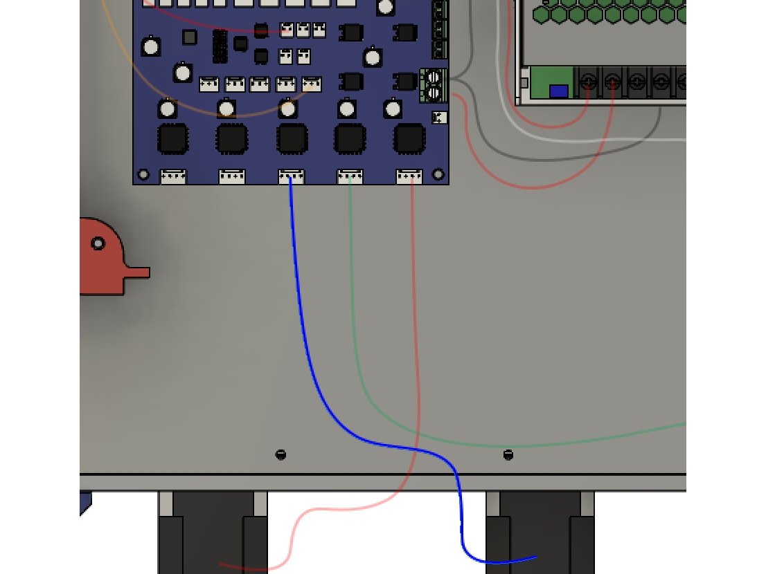
  • Connect all 3 Z stepper wires to the steppers. Route them so they can reach the stepper motors on the bottom edge of the Duex5, using zip ties and the zip tie mounts to hold them to the bottom panel.
  • Connecting these steppers to the correct ports is critical, otherwise your bed leveling will not work correctly.
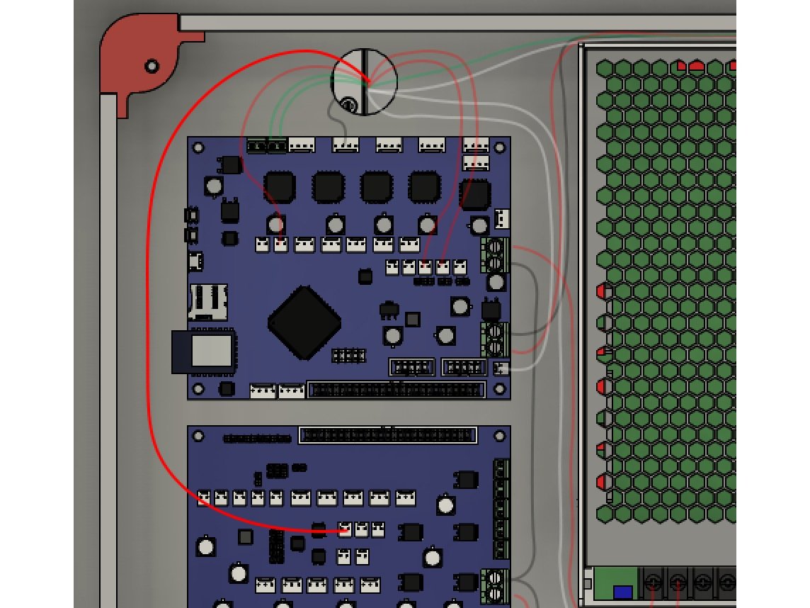
  • Connect the Front Left Z Stepper Cable to the Drive 5 port on the Duex5, which is labelled E2 MOT.

Step 33 — Rear Left Z Stepper

  • Connect the Rear Left Z Stepper to the Drive 6 port on the Duex5, which is labelled E3 MOT.

Step 34 — Right Z Stepper

  • Connect the Right Z stepper to the Drive 7 port on the Duex5, which is labelled E4 MOT.

R) Firmware, Config, and Smoke Test

Step 1 — A Word of Warning

  • Caution It can be tempting to rush ahead - you're almost done, after all, and you want to see your printer print. Don't rush these steps.
  • Caution Read each step carefully, and follow the instructions closely, you'll save yourself a lot of time and headache.
  • Caution If at any point you feel over your head here, stop and ask questions in the RailCore Discord (Best option) or RailCore Facebook group.
  • Caution Be very careful near your electronics with the cover off. You can install the cover first, but it can be difficult to adjust things, so I install it after the smoke test.
  • Caution NEVER UNPLUG ANYTHING FROM YOUR DUET WITH THE POWER ON, ESPECIALLY STEPPERS.

Step 2 — Default Config Files

  • Your Duet comes with an SD Card pre-loaded with configuration files. We need to change those to the RailCore default files.
  • Remove the SD card and put it in your PC. On it you'll find a series of folders.
  • Make a copy of the "sys" folder, and call it "sys_original".
  • Caution If your Kit came with RRFv2 installed: Copy all of the files from here into your sys folder, overwriting the original files: https://www.dropbox.com/sh/dmguq264vp7aw...
  • Caution If your Kit came with RRFv2 installed: Copy the files here into the /macros folder: https://www.dropbox.com/sh/gp2ur784zapus...
  • Caution If your Kit came with RRFv3 installed: Copy all of the files from here into your sys folder, overwriting the original files: https://www.dropbox.com/sh/6hvt9u44logql...
  • Caution If your Kit came with RRFv3 installed: Copy the files here into the /macros folder: https://www.dropbox.com/sh/rnumrdwvmmmqo...
  • Eject the SD card from your PC, and put it back in the Duet.

Step 3 — Connecting to your Duet

  • Before powering-on the first time, You need to connect to your duet with a microUSB cable.
  • Follow the instructions here for getting connected to your Duet: https://docs.duet3d.com/en/How_to_guides... You can use YAT as suggested, or any other serial console program.
  • Don't worry about upgrading your firmware yet, but take note of the version installed.
  • Send an M115 command to your Duet, be sure you see "Duet 2 WiFi + Duex 5" in the output.
    • If you do not see Duex 5, STOP. Your Duet to Duex5 ribbon connector is not working. Disconnect the USB to shut off the Duet and fix it before proceeding.
  • Continue following the instructions to get the Duet connected to your network.
  • Ensure that you can reach your Duet via Duet Web Control before disconnecting the USB. When you unplug the USB the duet will lose power.

Step 4 — Smoke Test

  • Double check all your connections.
  • Double check them again.
  • Once the printer is powered, do not work on the electronics until you power it off. Keep your fingers entirely away from the electronics area while the printer is on.
  • Connect the power cord to the IEC inlet plug.
  • Power on the printer.
  • You should be able to connect to the web interface you set up earlier.

Step 5 — Updating the Duet Firmware

  • Connect to your Duet via the web interface.
  • Navigate to the Settings, Machine Specific and look under Electronics to see your Firmware version. Under Settings, General you can see the Duet Web Control (DWC) version. If you're not at Reprap Firmware 2.05.1, DuetWebControl 2.0.7, and DuetWiFiServer-1.23 (for WiFi versions), follow the steps below to upgrade.
    • Download Duet2Firmware-2.05.1.zip and aip4e.bin from https://github.com/Duet3D/RepRapFirmware...
    • In the Duet Web Control GUI, navigate to the "System" section and select UPLOAD SYSTEM FILES.
    • Upload iap4e.bin into System files. (It might be there already.)
    • Upload Duet2Firmware-2.05.1.zip and reboot when prompted. Note that the .zip file should be sent as-is, and not extracted on your PC.
    • Check your firmware versions in the GUI to make sure they match the expected versions.

Step 6

  • Now is a good time to install your top and left panels. Each gets (4) M3 x 16mm button head bolts, (4) m3 washers, and (4) m3 nuts.
  • Install your Ebox Cover using (4) M3 x 8mm button head bolts.

S) First Moves

Step 1 — Safety Warning

  • Caution This section is written to be followed in order. DO NOT SKIP STEPS. Complete each step before moving on to the next.
  • Caution Your hotend fan should be turning when power is on if you connected it to an always on fan port as instructed. If not stop, power off, and fix it.

Step 2 — X (Rear) Stepper Direction

  • These instructions are documented here as well: https://www.duet3d.com/wiki/Configuring_...
  • Starting with the hotend over the center of the bed, issue the following in the "console" window of the Duet Web Control
    • G91
    • G1 H2 X10 F3000
  • That should move your Hotend in +X +Y (towards the right and back of the printer)
  • If your hotend moves -X -Y (Left and front), find this line in the config.g and change the S0 to S1:
    • M569 P0 S0
  • Caution If the Y (front) stepper moves, you have the steppers in the wrong ports. Power Down and change the cables to the correct ports - see the wiring instructions.

Step 3 — Y Stepper Direction

  • This is much the same as the X stepper.
  • In the console window of Duet Web Control, run the following:
    • G91
    • G1 H2 Y10 F3000
  • This should move the hotend in the +X and -Y Directions (towards the right side of the printer, and front of the printer)
  • If it does not, find this line in your config.g value, and change the S1 to S0
    • M569 P1 S1

Step 4 — Z Stepper Direction

  • Caution Be sure your bed is not close to your hotend before doing this. If it is, power down and move your bed down at least 15mm by turning the leadscrews.
  • In the gcode console in duet web control, run this:
  • G1 Z10 H2
  • This should move your bed DOWN away from the hotend 10mm.
  • If your Bed moves up, find the M569 P5 - 7 lines in your config.g file, and change the S0 to S1 for all 3 lines.
  • Caution If only some steppers move the wrong direction, skewing the bed, you need to edit the lines only for those steppers.

Step 5 — Test X endstop

  • In the console for Duet Web Control, issue this gcode:
    • M119
  • It should return "Endstops - X: not stopped, Y: not stopped, Z: no endstop, Z probe: not stopped"
  • Hold in the button on the X endstop switch (the one to the rear left of the printer, and run M119 again.
  • You should now get "Endstops - X: stopped, Y: not stopped, Z: no endstop, Z probe: not stopped"
  • Caution If none of the endstops show as stopped, check your X endstop connection
  • Caution If the Y endstop shows as stopped, you have the endstops in the wrong ports. Power down and double check they're plugged in correctly.

Step 6 — Test Y Endstop

  • In the console for Duet Web Control, issue this gcode:
    • M119
  • It should return "Endstops - X: not stopped, Y: not stopped, Z: no endstop, Z probe: not stopped"
  • Hold in the button on the Y endstop switch (the one near the hotend) and run M119 again.
  • You should now get "Endstops - X: not stopped, Y: stopped, Z: no endstop, Z probe: not stopped"
  • Caution If the Y endstop does not show as stopped, check your Y endstop wiring.

Step 7 — BLTouch Testing

  • Your BLTouch should be on, with a solid red light. If it's flashing, power off and check its wiring.
  • Run the following gcode in the console in duet web control:
    • M280 P3 S10
  • The pin on the bltouch should lower. (Look across the nozzle of your hotend at the pin, it should extend below the nozzle, this is important for leveling!)
  • Tapping the pin lightly with your fingertip should cause it to retract, then drop back down.
  • Running the following gcode should retract the pin again:
    • M280 P3 S90
  • The Z Probe value in the duet web control should read zero.

Step 8 — X Homing Test

  • Caution When running the following commands, a lot can go wrong. Keep your finger near the power switch just in case. Read all of the instructions before beginnging.
  • Test homing X by running the following in the gcode console:
    • G28 X
  • Your printer should move to the left until it contacts the X endstop.

Step 9 — Y Homing Test

  • Caution When running the following commands, a lot can go wrong. Keep your finger near the power switch just in case. Read all of the instructions before beginnging.
  • Test Homing Y by running the following in the gcode console:
    • G28 Y
  • Your hotend should move towards the front of the printer until the Y endstop triggers against the front X carriage.

Step 10 — Z Homing Test

  • Caution When running the following commands, a lot can go wrong. Keep your finger near the power switch just in case. Read all of the instructions before beginnging.
  • Move the bed at least 50mm below the nozzle by running this command in the gcode console (if it's already low enough, skip this)
    • G1 H2 Z50
  • Trigger the homing of the bed by running this in the gcode console:
    • G28 Z
  • The bltouch pin should drop, and the bed should start to move up. Tap the bltouch pin with your fingertip. It will raise and lower, tap it again. This should stop the bed.
  • Caution If the bed does not stop, hit the power button immediately.
  • If the bed stops as expected, re-run G28 Z to properly home the bed. Keep ready to hit the power switch in case something does not work.

Step 11 — Bed leveling

  • Assuming all of the previous homing tests have worked, or any issues encountered have been resolved, you can now proceed with automated homing and bed leveling.
  • Power off the printer, and adjust the bed manually by turning the leadscrews until it's close to level. It does not have to be perfect, but should be close.
  • Power on the printer, and run the following to home all 3 axis:
    • G28
  • To level the bed, send the following gcode:
    • G32
  • The printer should probe 4 points on the bed, and return a status of the adjustments made.

T) Adjusting Your Configuration

Step 1 — Adjusting the Z probe height

  • Home all 3 axis, and level the bed. Run G32 at least 3 times, so your bed is as level as it can be.
  • Run G28 Z to return to the center of the bed. Your bed will move to Z10.
  • Run the following gcode, so we can move below Z0 if needed:
    • G92 Z12
  • Place a sheet of paper on your bed.
  • Using the jog buttons in duet web control, slowly jog down until your nozzle just contacts the paper (slide the paper around until you can feel the nozzle touching it. Use the smallest steps as you get close)
  • Remove the piece of paper, and run the "Probe Point" macro (click on the macro and it will ask you if you want to run it)
  • The printer will re-home Z, stopping when the probe triggers.

Step 2 — Adjusting the Z Probe Height - Continued

  • In duet web control, find the current Z height value, and record it.
  • Edit your config.g file, towards the end of it find the following line
    • G31 X2 Y42 Z2.65 P25
  • Edit the Z value, put in the value from Duet Web control.
  • Save the config.g and restart.

Step 3 — Adjusting Max X / Y / Z

  • You can break your printer with this step, be cautious.
  • Run this command to allow movement beyond what the printer is physically capable:
    • M208 X400 Y400 Z700
  • Use the jog buttons in duet web control to slowly jog the hotend to max Y. Stop just before it hits the rear X carriage, and record the value.
  • Use the jog buttons in duet web control to slowly jog the hotend to max X, near a leadscrew. Stop before it contacts a leadscrew with the fan. Record the X value.
  • Use the jog buttons in duet web control to slowly move the bed down by increasing the Z height. Stop before the bed contacts the Z couplers, and record the Z height.
  • Jog the bed back up, and center the hotend.
  • Find this line in your config.g and replace the values with the ones you recorded: M208 X290 Y290 Z280

Step 4 — Hotend PID tuning

  • Caution This will heat your hotend up. Stay near your printer in case of problems.
  • Caution Be sure your hotend is not near your bed, or touching anything.
  • Run this command:
    • M303 H1 S250
  • Your hotend will go through a PID tuning cycle. When it's done, run M307 H1 to see the values, it will report something like this:
  • Heater 0 model: gain 199.0, time constant 962.6, dead time 4.5, max PWM 1.00, calibration voltage 24.2
  • Using that as an example, find the M307 H1 line in your config.g and adjust it as follows, using the values for gain, time constant, dead time, and voltage from your M307 output
  • M307 H1 A199.0 C962.6 D4.5 V24.2 B0

Step 5 — Bed PID Tuning

  • Caution This will heat your bed up. Stay near your printer in case of problems.
  • Caution Be sure nothing is on your bed.
  • Run this command:
    • M303 H0 S60
  • Your bed will go through a PID tuning cycle. When it's done, run M307 H0 to see the values, it will report something like this:
  • Heater 0 model: gain 170.9, time constant 771.5, dead time 4.5, max PWM 1.00, calibration voltage 24.1
  • Using that as an example, find the M307 H0 line in your config.g and adjust it as follows, using the values for gain, time constant, dead time, and voltage from your M307 output.
  • M307 H0 A170.9 C771.5 D5.2 V24.1 B0

Step 6 — Hot Tighten Your Nozzle

  • E3D strongly recommends tightening your nozzle while hot.
  • To do so, after you've PID tuned, run the following to allow your hotend to go above 280C
    • M143 S295
  • Run this to set your hotend to 285C, or set it in the DWC interface
    • M104 S285
  • Once your hotend is at 285C carefully tighten the nozzle
  • Once tightened, turn off your hotend in Duet Web Control

Step 7 — Test the Extruder Direction

  • Attach the PTFE guide tube to the extruder input, and pass the other end through the PTFE holder on the right side of the printer.
  • Set your hotend to an appropriate temperature for your filament.
  • Feed some filament in through the feed tube, until it reaches the extruder.
  • Using the DWC interface, slowly extrude some filament, it should grab the filament and pull it in.
  • If instead it pushes the filament back out, find this line in your config.g and change the S0 to an S1
    • M569 P3 S0

Step 8 — Increasing the Z homing Speed

  • A common request is to increase the speed the Z axis homes. Be careful with this change, you can damage your printer.
  • Edit the config.g file and find the following line
    • M558 P9 X0 Y0 Z1 H5 F50 T6000 A5 S0.02
  • Change the "F50" value to a higher value to increase the speed. "F100" is twice as fast.
  • A value of F150 should suffice without being too fast to break anything if homing is already confirmed working.

Step 9 — Extra Fasteners

  • Railcore kits include extra hardware, don't be alarmed that you've reached the end and have some left - they're spares!