Q) Wiring the Electronics
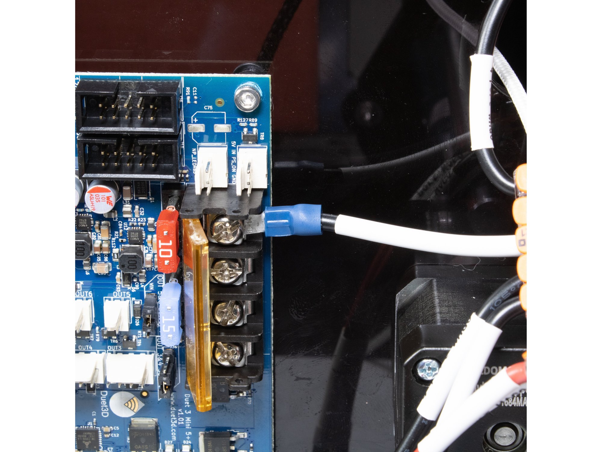
Step 1 — Power Duet
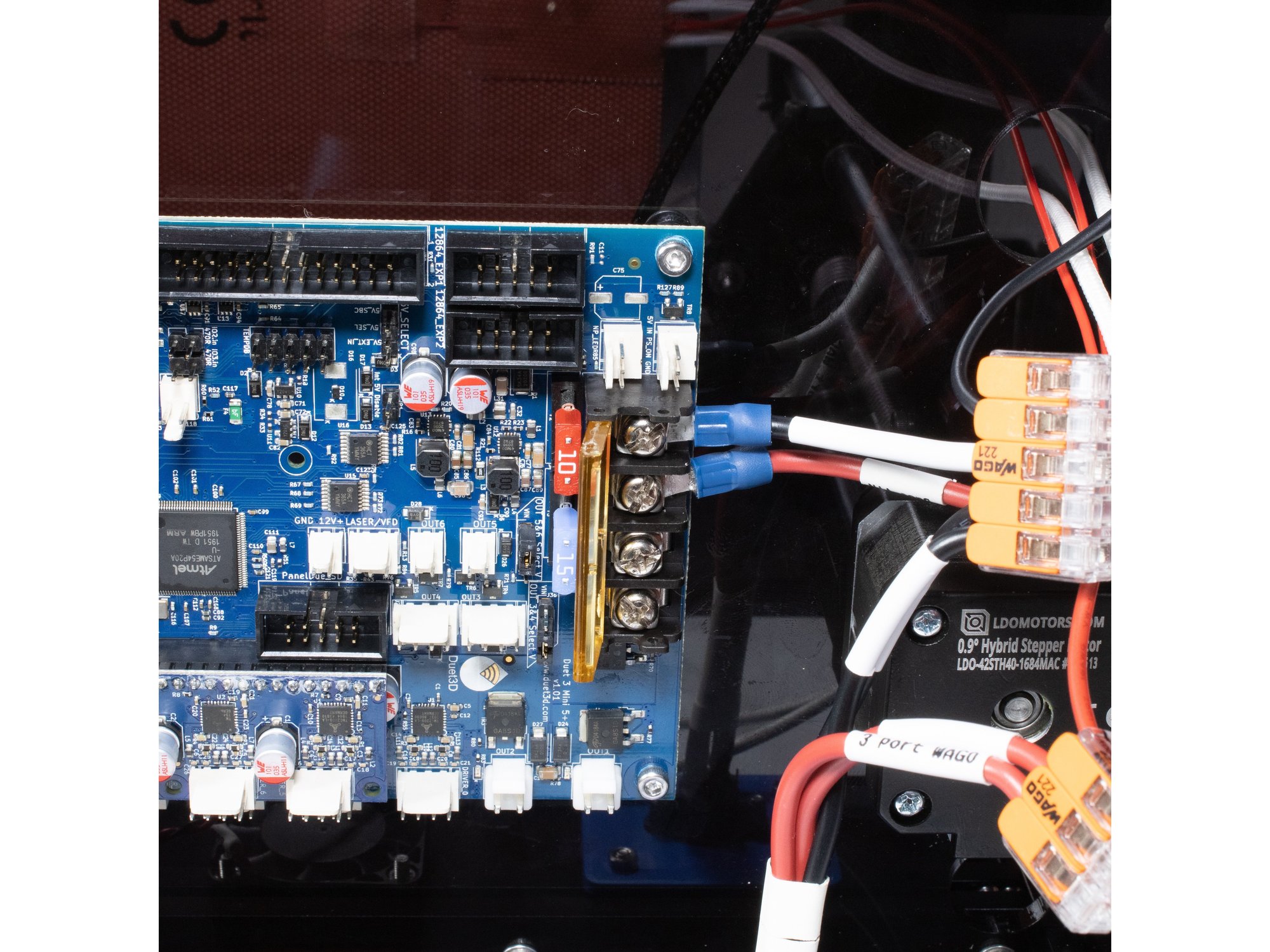
- The black wire labeled Duet GND from the 6 slot Wago connector attaches to the first GND on the Duet.
- The red wire labeled Duet 24v from the 3 slot Wago connector attaches to the first VIN terminal on the Duet.
Step 2 — Power Bed
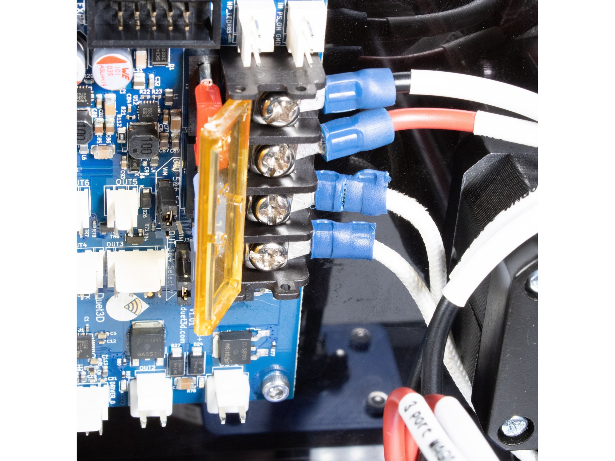
- The ring terminals coming from the bed should attach to the remaining terminals (OUT 0).
Step 3 — Bed Thermistor
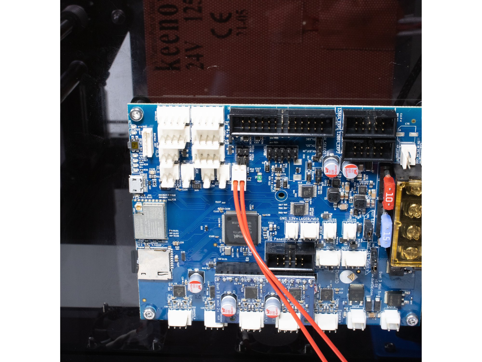
- The bed thermistor connects to Temp 0.
Step 4 — Hotend Thermistor
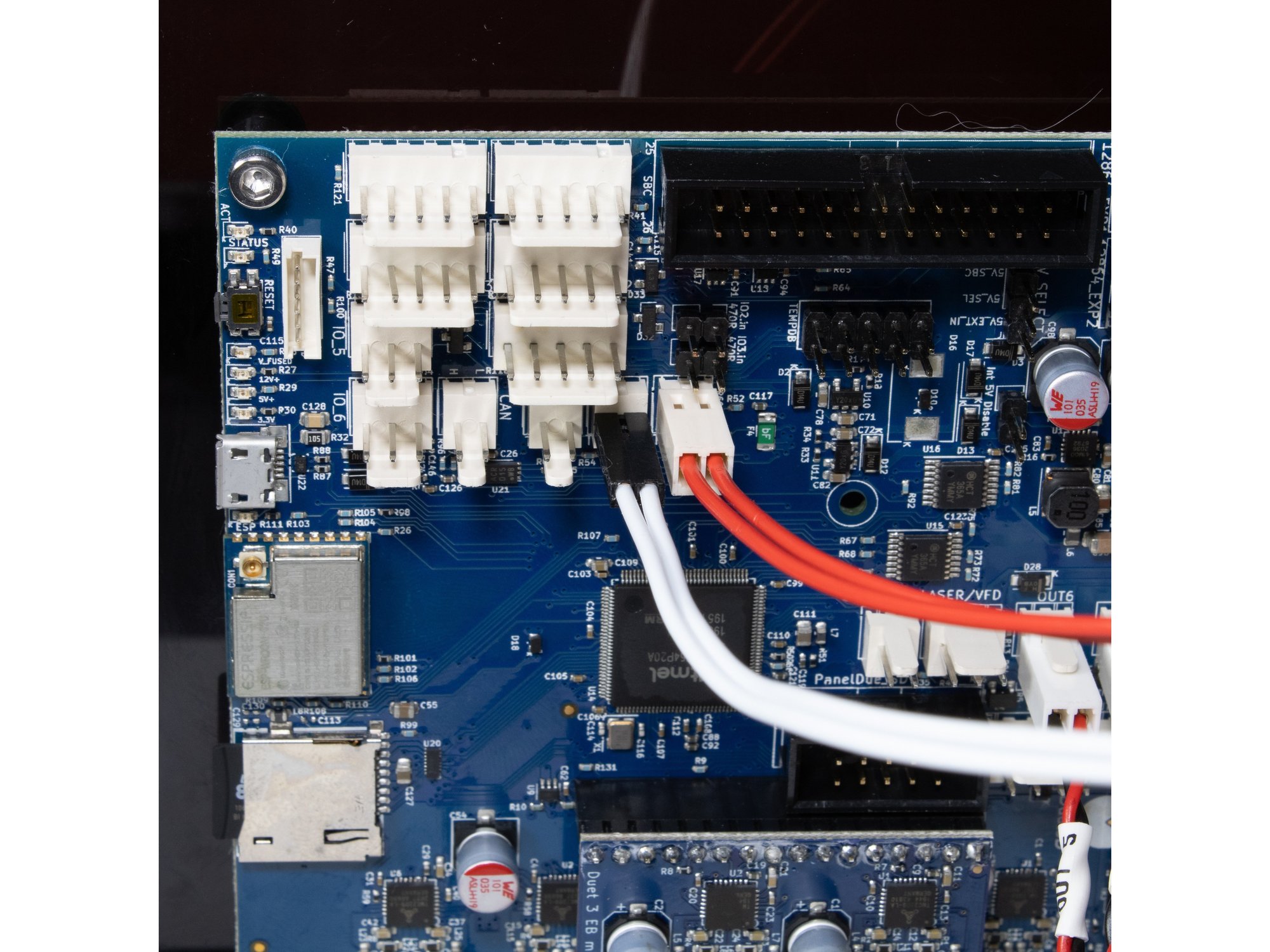
- The hotend thermistor plugs into temp1 .
Step 5 — End Stops
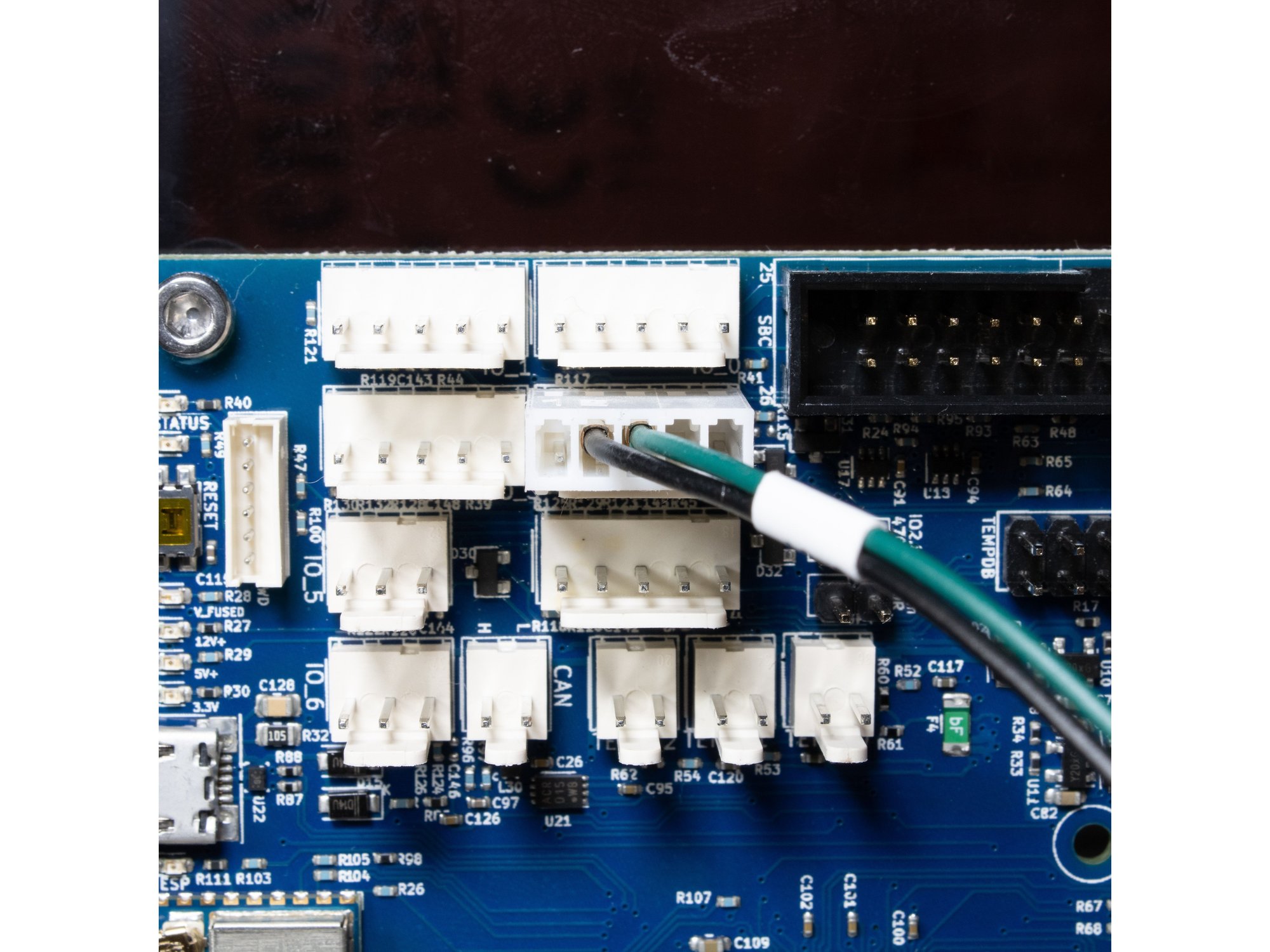
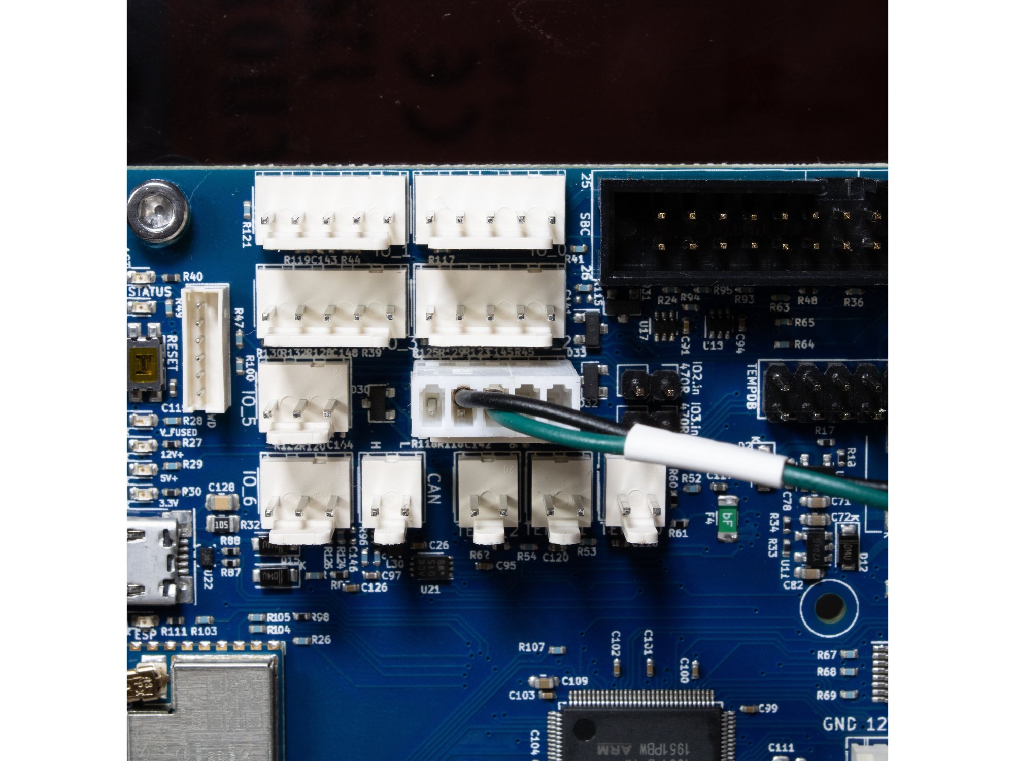
- Wire the X endstop to io.2.
- Wire the Y endstop to io.4.
Step 6 — Fans
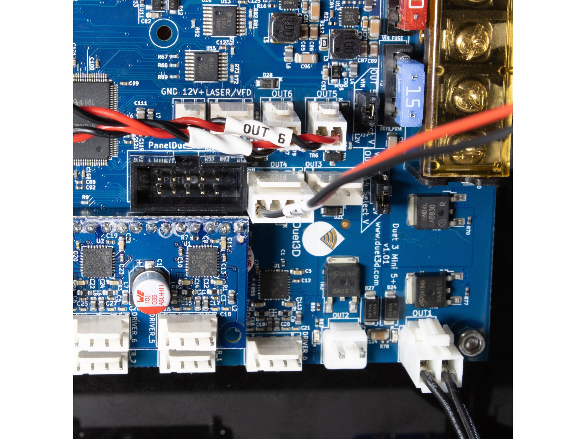
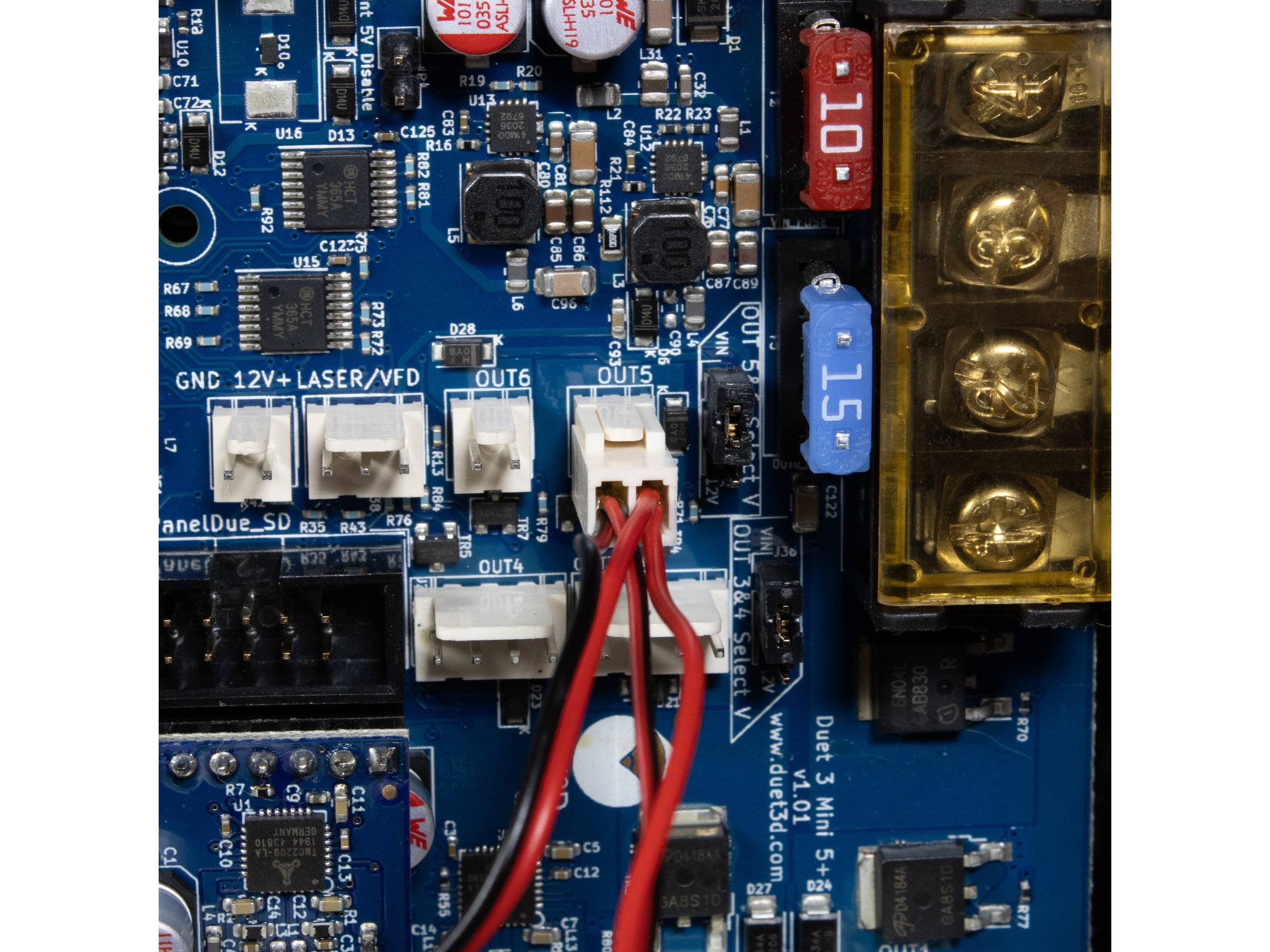
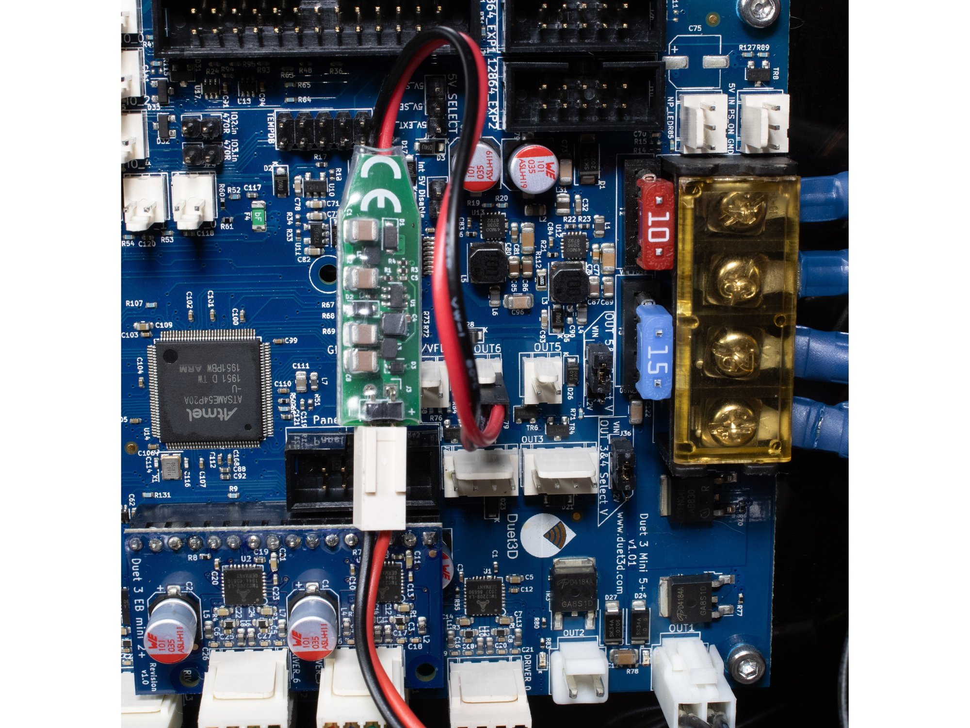
- Wire the layer fan to out4.
- Panel fans are wired to out5.
- Hotend fan is wired to out6.
- Caution If you are using the E3D Revo Micro, your hotend fan must use the included 24v -> 5v buck converter.
Step 7 — Hotend Heater
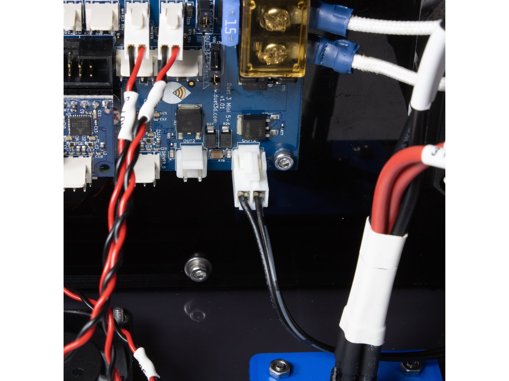
- The hotend heater is wired to out1.
Step 8 — BLTouch
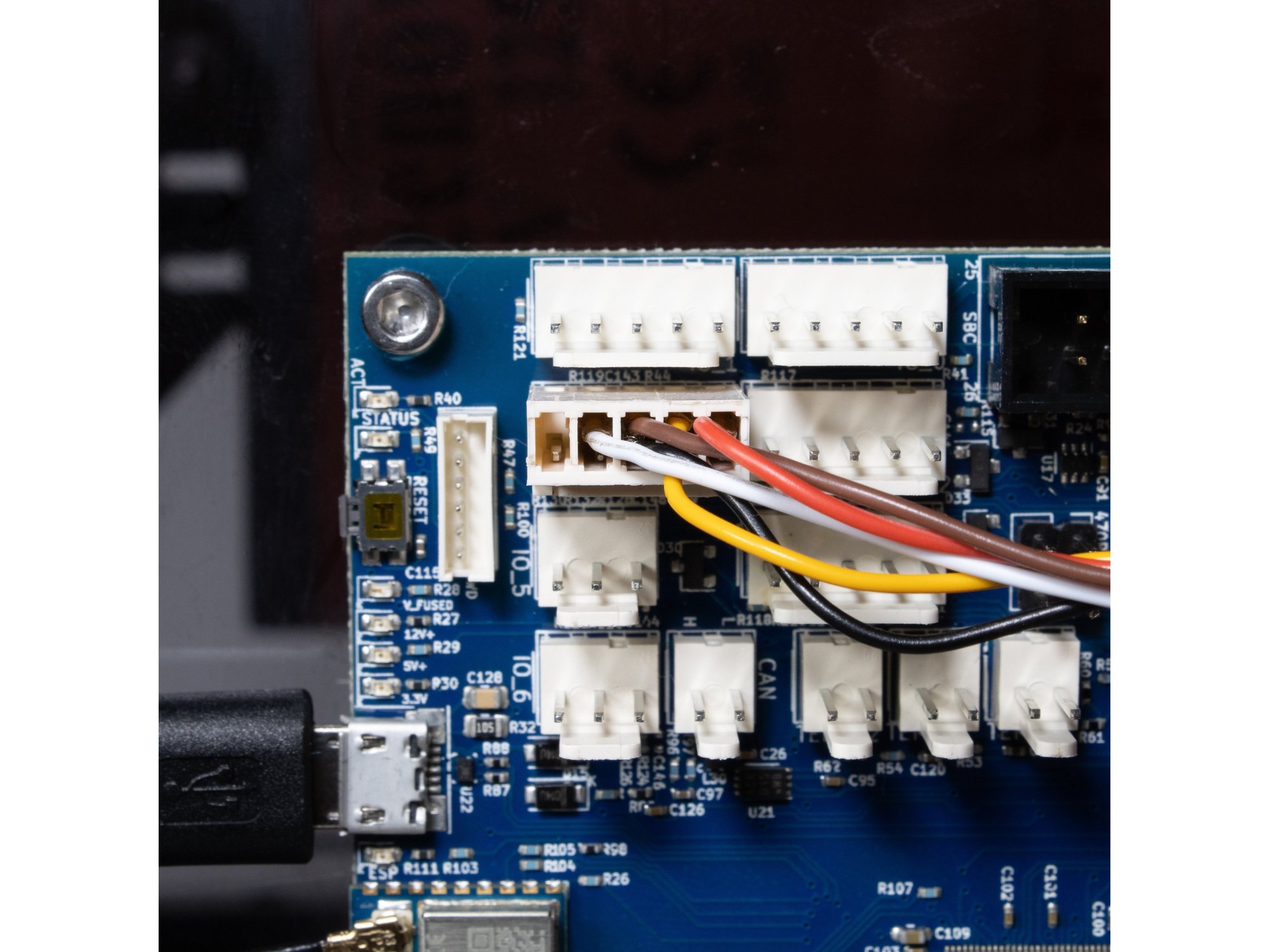
- The BLTouch is wired to io3.
Step 9 — Extruder
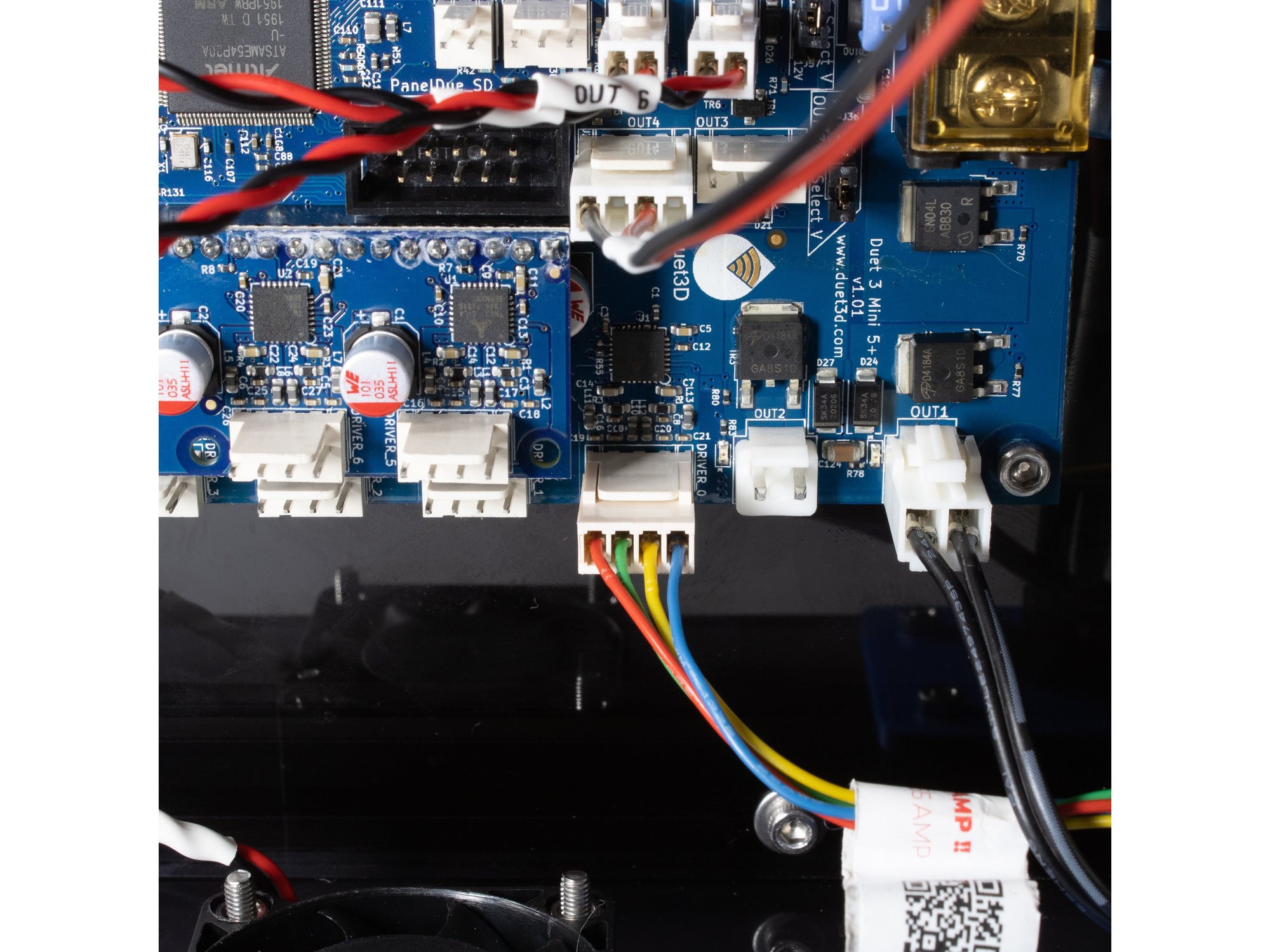
- The extruder is wired to Drive 0.
Step 10 — Z Axis
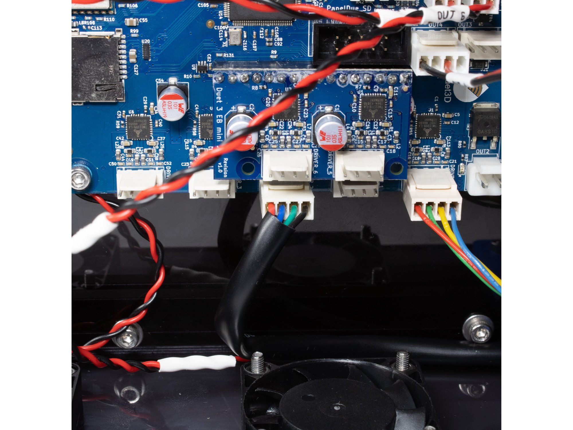
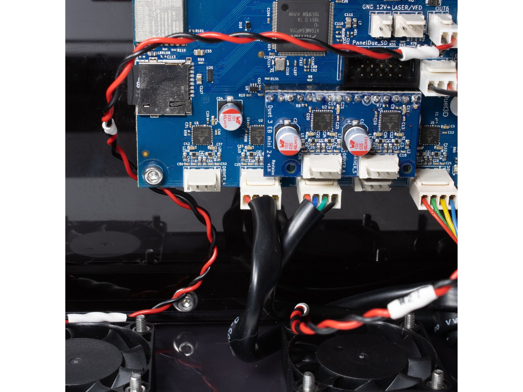
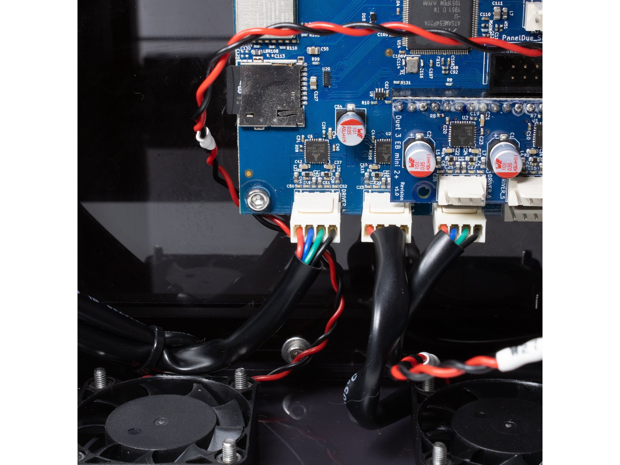
- Front right Z stepper is wired to Drive 2.
- Rear right Z stepper is wired to Drive 3.
- Left Z stepper is wired to Drive 4.
Step 11 — X/Y Axis
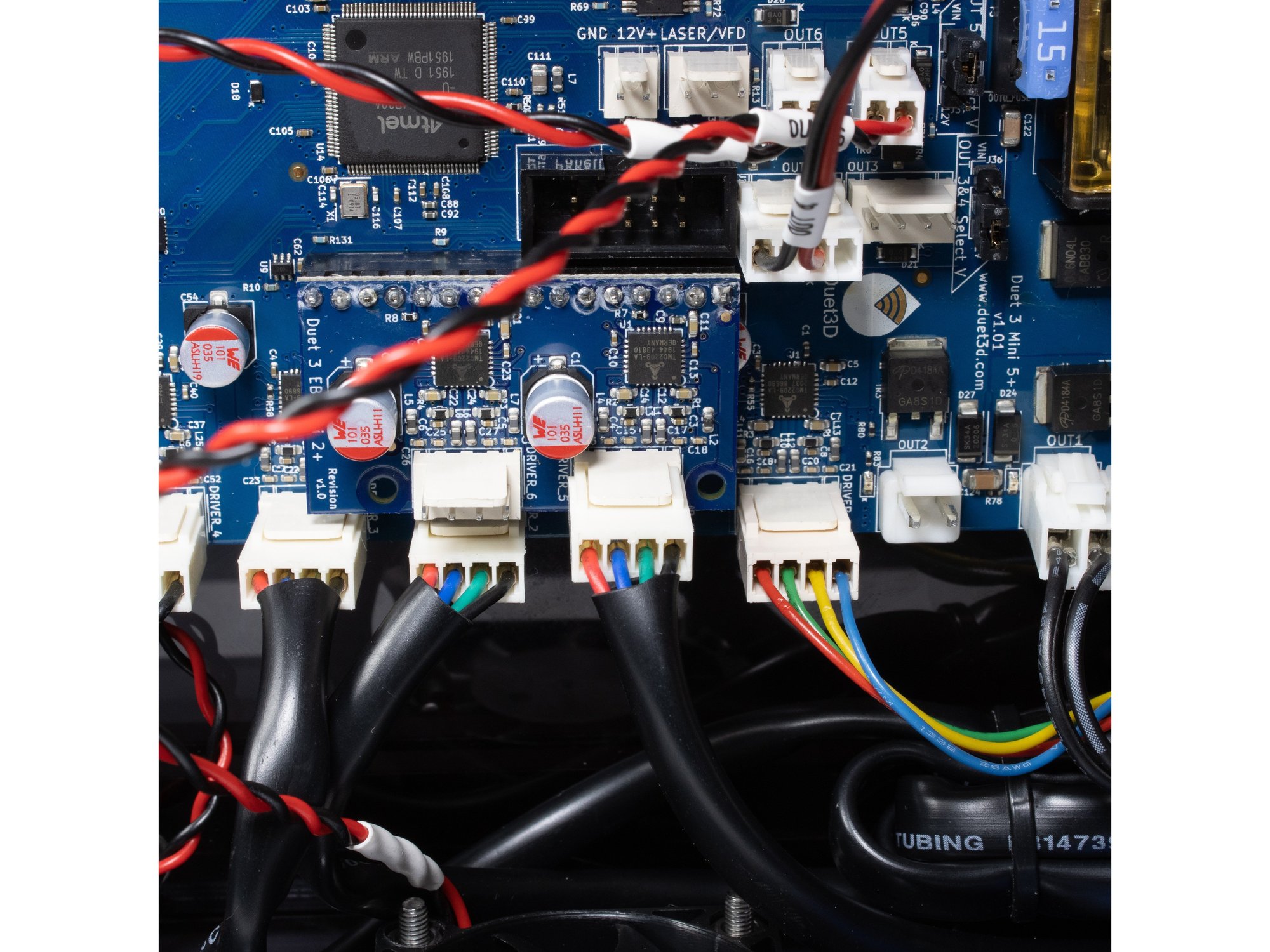
- X stepper (front) is wired to Drive 5 on the expansion board.
- Y stepper (rear) is wired to Drive 6 on the expansion board. This is the last free driver on the expansion board.
Step 12 — WiFi Antenna
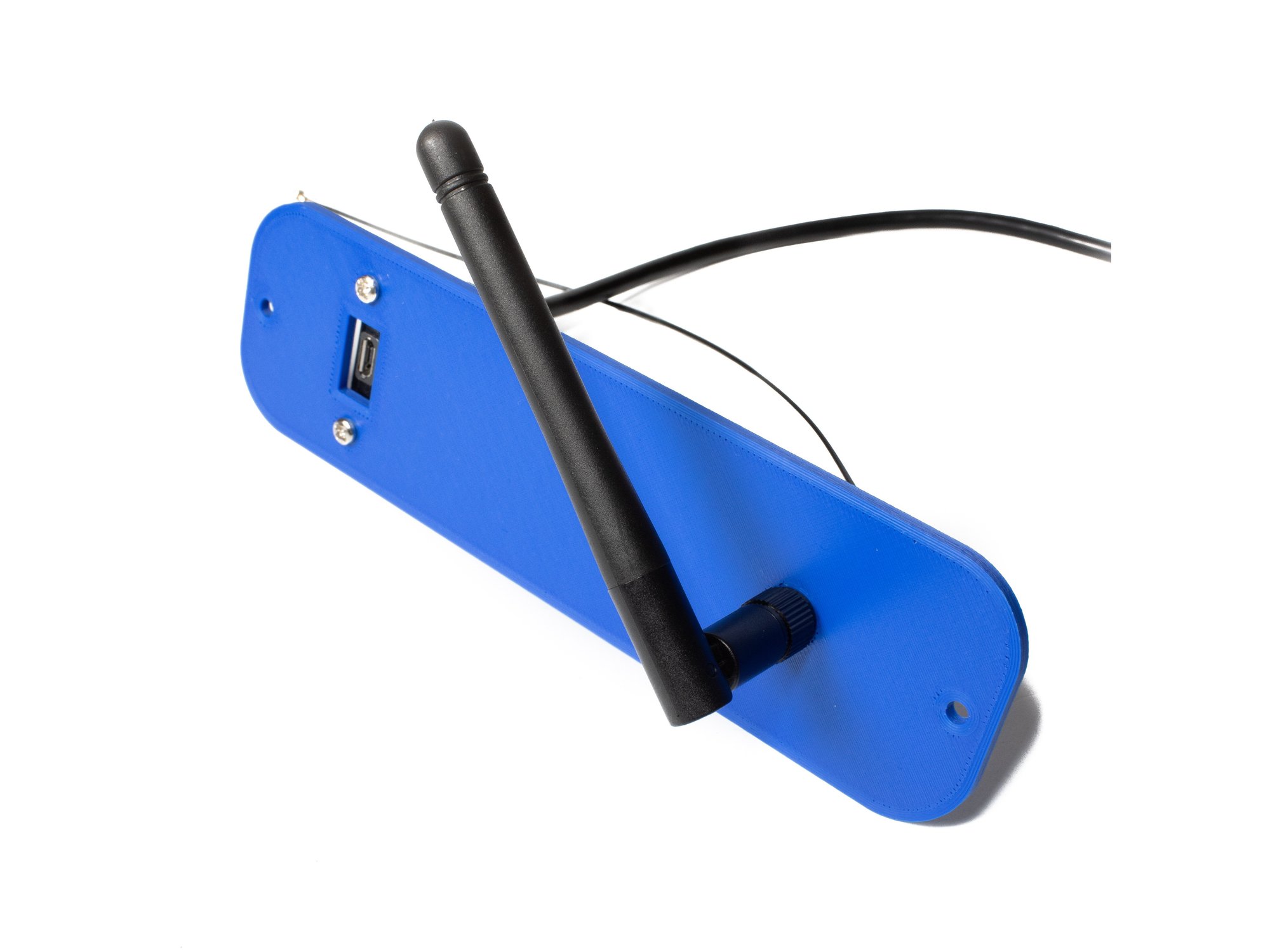
- Using (2) M3 x 10 socket head screws, washers and nuts, attach the antenna and USB extender to the outside of the printer panels.
- Plug the USB extension and WiFi pigtails into the Duet.
- Note https://duet3d.dozuki.com/Wiki/Getting_S...
Originally at https://railcore.dozuki.com/Guide/Q)+Wiring+the+Electronics/39