RailCore® Labs

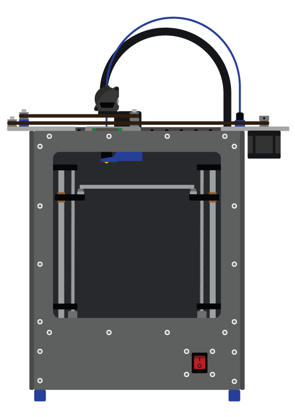
RailCore® is a family of Core-XY based Reprap 3D printers designed by J. Steve White, Tony Akens, and Ben Withem.
New Z alignment procedure for the Z extrusions.
Looking for some folks to help test this. If you have what appears to be Z banding, give it a shot. First, print this part (I recommend printing a few of them, it’s small).
To do this, you have to do the following steps (assuming a functional RailCore)
- Remove your bed
- Remove a leadscrew from the anti-backlash nut. Leave the bottom of the AB nut on. (unless you have the lower half of the nut on the bottom side of the yoke. if so, remove it)
- Remove your leadscrew coupler
- place the printed part over your stepper motor shaft. It will be a very tight fit, seat it fully.
- lower your yoke - ideally the hole for the leadscrew will fall nicely over the printed part. If so, you’re well aligned. Mine did not.
- loosen all 7 nuts on the top and bottom Z brackets.
- adjust until the yoke fits nicely over the alignment tool. BE CAREFUL YOUR CARRIAGE DOESN’T GO OFF THE END OF THE RAIL
- push the lower part of the Z extrusion firmly against the outside frame extrusion.
- tighten the lower Z bracket
- make sure the yoke still slides nicely on and off the alignment tool
- use a square, or 123 blocks to square the top of the Z extrusion to the frame.
- Tighten down the top bracket, making sure the Z extrusion is tight against the frame.
- Remove alignment tool
- reinstall coupler
- reinstall Leadscrew
This is pretty much the same process as before, but the alignment tool is a much more rigid attachment and alignment point and should give MUCH better alignment. It helped all of my leadscrews.
Another tip: test you can fit it on a spare stepper shaft BEFORE you pull your printer apart. Especially if you don’t have a second printer to print a new one.
It’s just a 5mm hole in one end of a 10.35mm diameter cylinder, 25mm long.